Light diffusion plate and lighting device

A technology of light diffusion plate and diffusion plate, which is applied in the field of diffusion plate

Pending Publication Date: 2021-04-13
ZHEJIANG CARBON VISION TECH CO LTD
View PDF0 Cites 2 Cited by
  • Summary
  • Abstract
  • Description
  • Claims
  • Application Information

AI Technical Summary

Problems solved by technology

[0005] Based on this, it is necessary to provide a light diffusion plate and a lighting device for the p

Method used


Image

  • Light diffusion plate and lighting device
  • Light diffusion plate and lighting device
  • Light diffusion plate and lighting device

Examples


preparation example Construction

[0048] The preparation method of the above-mentioned light diffusion plate in one embodiment is as follows:

[0049] 1. Mix and granulate the slices and additives used to prepare the diffusion plate body, the first microstructure layer and the second microstructure layer respectively in a twin-screw extruder to prepare masterbatches respectively. The temperature of each section of the twin-screw extruder is as follows: the temperature of the first zone is 160-220°C, the temperature of the second zone is 200-280°C, the temperature of the third zone is 195-275°C, the temperature of the fourth zone is 195-275°C, and the temperature of the fifth zone is 190-270°C °C, the temperature in the six zones is 190-270 °C, and the temperature of the machine head is 185-265 °C.

[0050] 2. Mix the above-mentioned masterbatch with the slices used to prepare the diffusion plate body, the first microstructure layer and the second microstructure layer in a certain proportion, and then put them ...

Embodiment 1

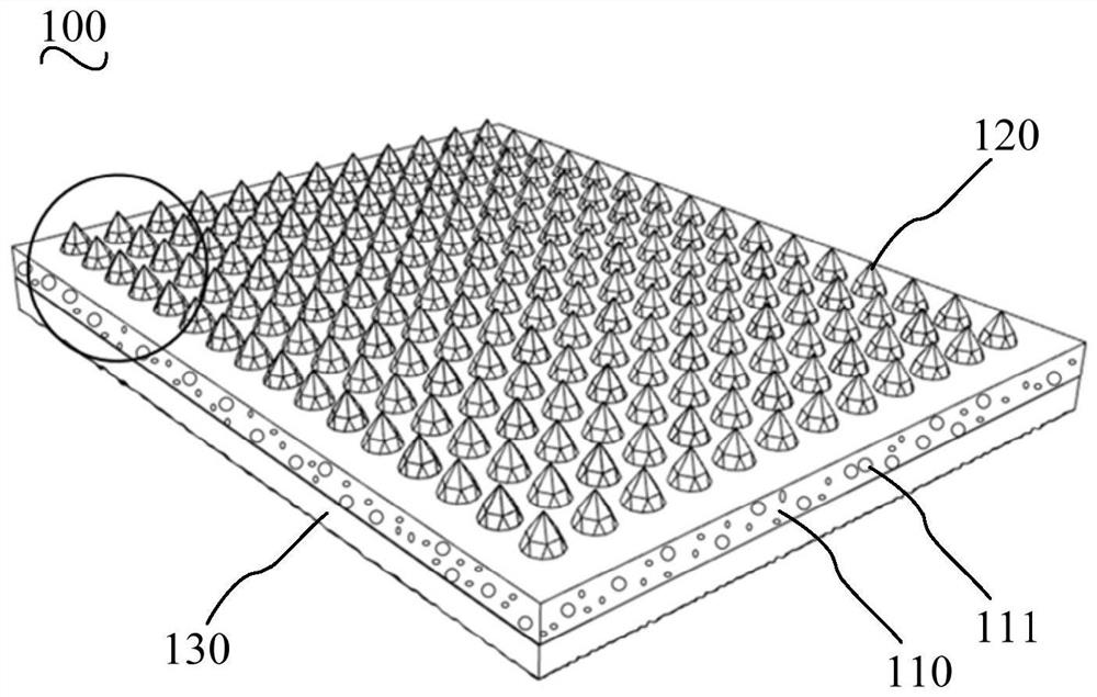
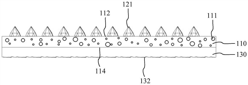
[0057] The light diffusion plate of embodiment 1 includes a diffusion plate body, a first microstructure layer and a second microstructure layer.

[0058] There are a number of diffusion particles in the diffuser body, and the diffuser body includes a light-incoming surface and a light-emitting surface. Wherein, the diffusion particles are organic silicon particles with a diameter of 1 μm. The thickness of the diffusion plate body is 0.6mm.

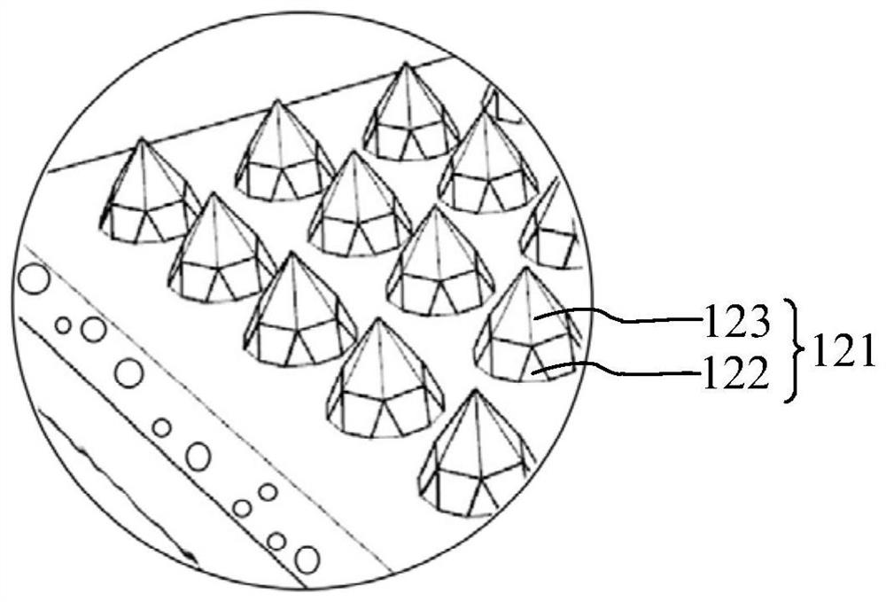
[0059] The first microstructure layer is located on the side of the light-incoming surface of the diffusion plate body, and the first microstructure layer includes several microstructures. The microstructures include prisms on the light-incoming surface and pyramids on the prisms; The bottom surface coincides with the bottom surface of the pyramid, and the sides of the prism are arranged alternately by triangles and trapezoids. The apex of the triangle away from the diffusion plate body coincides with the apex of the bottom surface of th...

Embodiment 2

[0062] The light diffusion plate in embodiment 2 includes a diffusion plate body, a first microstructure layer and a second microstructure layer.

[0063] There are a number of diffusion particles in the diffuser body, and the diffuser body includes a light-incoming surface and a light-emitting surface. Wherein, the diffusion particles are organic silicon particles with a diameter of 1 μm. The thickness of the diffusion plate body is 0.6 mm.

[0064] The first microstructure layer is located on the side of the light-incoming surface of the diffusion plate body, and the first microstructure layer includes several microstructures. The microstructures include prisms on the light-incoming surface and pyramids on the prisms; The bottom surface coincides with the bottom surface of the pyramid, and the sides of the prism are arranged alternately by triangles and trapezoids. The apex of the triangle away from the diffusion plate body coincides with the apex of the bottom surface of t...


PUM

PropertyMeasurementUnit
Bottom side lengthaaaaaaaaaa
Heightaaaaaaaaaa
Heightaaaaaaaaaa

Abstract

The invention relates to a light diffusion plate and a lighting device. The light diffusion plate comprises a diffusion plate body, a first microstructure layer and a second microstructure layer; a plurality of diffusion particles are arranged in the diffusion plate body; the diffusion plate body comprises a light entering surface and a light outgoing surface; the first microstructure layer is located on one side of the light entering surface of the diffusion plate body; the first microstructure layer comprises a plurality of microstructures; each microstructure comprises a prismoid located on the light entering surface and a pyramid located on the prismoid; the upper bottom surface of the prismoid coincides with the bottom surface of the pyramid; the side surface of the prismoid is formed by alternately arranging triangles and quadrangles; the vertex, away from the diffusion plate body, of each triangle coincides with the vertex of the bottom surface of the pyramid, and the other two vertexes of the triangle are located on the lower bottom surface of the prismoid; and the second microstructure layer is located on one side of the light outgoing surface of the diffusion plate body, and the surface, away from the diffusion plate body, of the second microstructure layer is provided with rough grains. According to the light diffusion plate, the utilization rate of a light source is increased, emergent light can be uniform and soft, the anti-dazzle effect is achieved while the light is uniformly transmitted, and application is better facilitated.

Description

technical field [0001] The invention relates to the technical field of diffusion plates, in particular to a light diffusion plate and an illuminating device. Background technique [0002] At present, with the gradual development of society, more and more light-emitting devices such as billboards, display screens and lamps will have the problem of uneven light emission due to the aggregation of point light sources or line light sources. Generally, the diffuser plate is used to solve the above problems because of its characteristics of high light diffusivity, high light transmittance and good light shielding properties. Its principle is to use light to refract, reflect and scatter when it encounters two media with different refractive indices (density) on the way. [0003] However, the existing diffusers cannot well solve the glare problem during use, especially when used in closed spaces such as offices, libraries, hospitals, schools and other public environments, the eyes w...

Claims


Application Information

Patent Timeline
IPC IPC(8): G02B5/02F21V5/00
CPCF21V5/002F21V5/005G02B5/0221G02B5/0231G02B5/0242
Inventor 不公告发明人
Owner ZHEJIANG CARBON VISION TECH CO LTD
Why Eureka
Try Eureka