
Motor controller and motor control method

A motor controller and motor control technology, applied in the direction of single motor speed/torque control, etc., can solve the problems of fan output air volume drop, fan working status influence, fan output air volume fluctuation, etc., to achieve constant air volume and self-adaptation Adjustment effect

Active Publication Date: 2013-09-18
GREE ELECTRIC APPLIANCES INC +4
View PDF6 Cites 18 Cited by
  • Summary
  • Abstract
  • Description
  • Claims
  • Application Information

AI Technical Summary

Problems solved by technology

[0010] However, with the application of brushless DC motors in the field of household appliances, especially the application of fans, the constant speed control method gradually shows its disadvantages. Influenced by the specific application of the equipment
The location and installation method of the equipment are different, and the structural characteristics of the air duct are also different. Under the same input conditions, the output air volume of the fan fluctuates greatly, and even cannot meet the basic air volume output requirements.
For example, in the use of range hoods, due to the different installation positions of the equipment, the length and angle of the air duct are also very different. When the wind resistance is large, the output air volume of the fan will vary when the motor speed remains constant. decline, even unable to guarantee the timely discharge of oil fume

Method used


Image

  • Motor controller and motor control method
  • Motor controller and motor control method
  • Motor controller and motor control method

Examples


Embodiment Construction

[0026] The single-phase DC brushless motor of this embodiment is applied to electrical equipment such as range hoods, fan coils, etc. It has a housing, a stator and a rotor are installed in the housing, and a rotor shaft is installed in the middle of the rotor. The motor is also equipped with a controller for controlling the operation of the single-phase brushless DC motor. The controller controls the current loaded to the stator coil winding, thereby controlling the rotor speed, thereby controlling the air output of the fan.

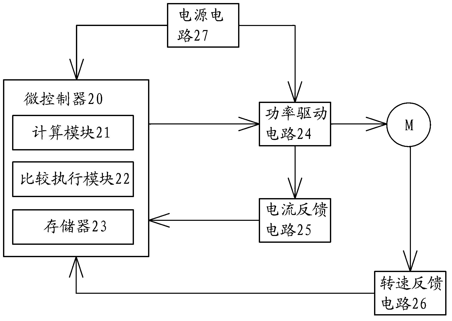
[0027] see figure 2 , The motor controller of the present invention has a microcontroller 20 , a power drive circuit 24 , a current feedback circuit 25 , a rotational speed feedback circuit 26 and a power supply circuit 27 . Wherein, the microcontroller 21 is a single-chip microcomputer, which receives an externally input control signal, and the control signal includes a set value. After receiving the set value, the microcontroller 20 generates a puls...


PUM


Abstract

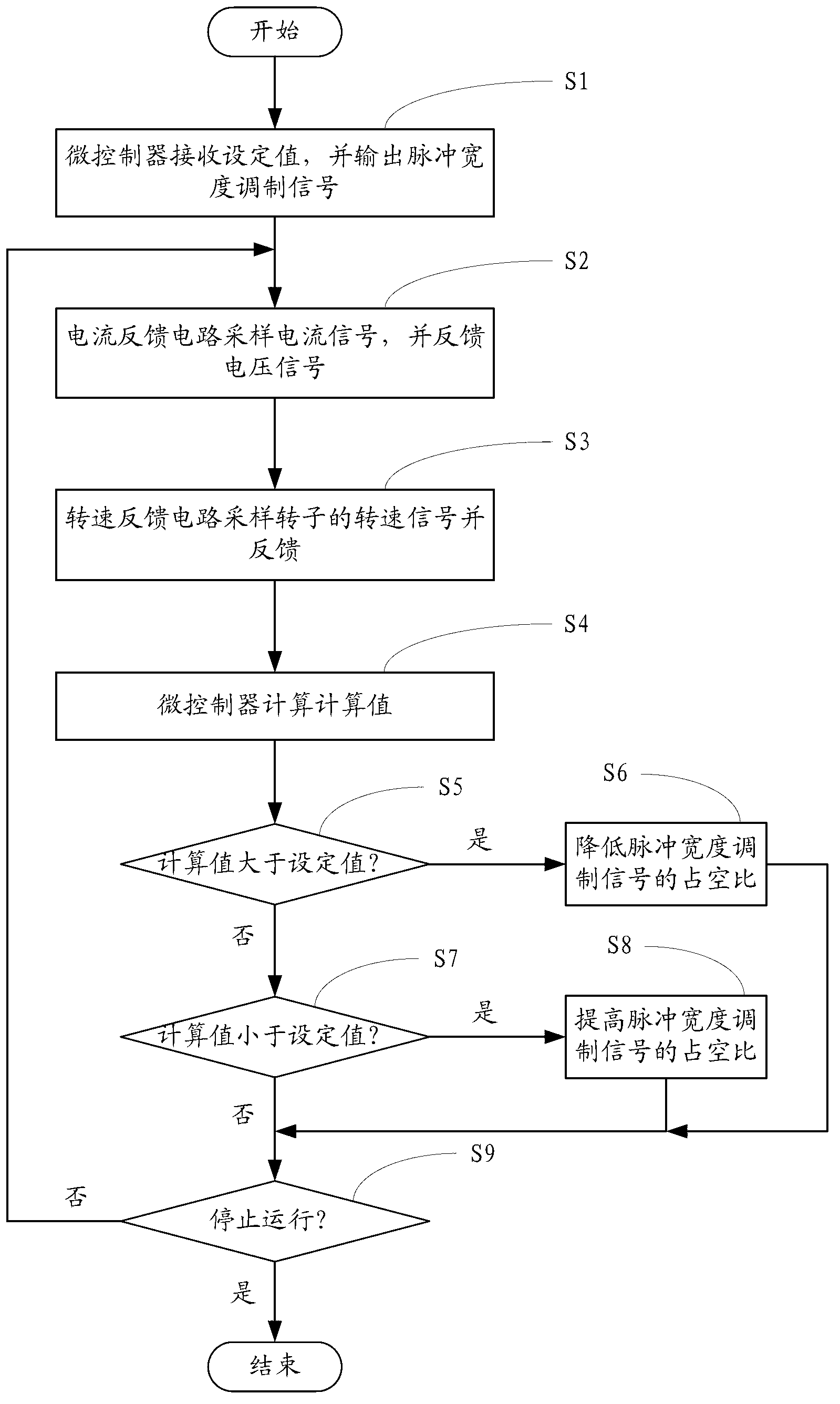
The invention provides a motor controller and a motor control method. The motor control method is that a microcontroller of the motor controller receives a set value and outputs a pulse width modulation signal to a power drive circuit according to the set value, a current feedback circuit of the controller samples a current signal passing the power drive circuit, converts the current signal into a voltage signal and outputs the voltage signal to the microcontroller, a rotating speed feedback circuit of the controller samples a rotating speed signal of a rotor of a sampled motor and outputs the rotating speed signal to the microcontroller, and the microcontroller calculates a calculated value according to a specific value of the voltage signal to the rotating speed signal and adjusts the duty ratio of the pulse width modulation signal output to the power drive circuit according to the size relationship of the calculated value and the set value. The controller controls the motor by means of the motor control method. The motor controller can ensure air volume of a fan to be kept constant when the motor is applied to a fan and meet the requirements of the fan in different application occasions.

Description

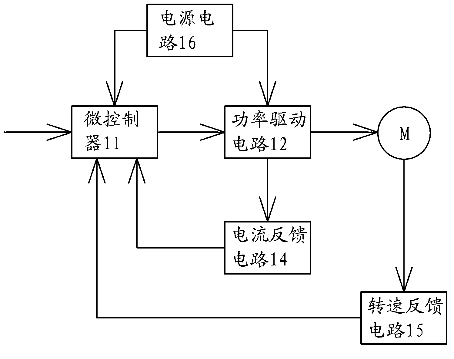
technical field [0001] The invention relates to the field of motors, in particular to a controller for a brushless DC motor and a control method for the DC brushless motor. Background technique [0002] Because of its advantages of continuous speed regulation, large starting torque, good mechanical characteristics, and good controllability, brushless DC motors are becoming more and more popular and have been widely used in various electrical equipment. In addition to being provided with a stator and a rotor, the brushless DC motor is also provided with a controller for controlling the operation of the motor, which is used to control the speed regulation and commutation of the brushless DC motor. The electrical principle block diagram of a controller of a brushless DC motor is as follows: figure 1 shown. [0003] The existing controller has a microcontroller 11, which receives an externally input speed regulation signal, and the signal contains a set value. After receiving...

Claims


Application Information

Patent Timeline
Patent Type & Authority Applications(China)
IPC IPC(8): H02P6/08
Inventor 李宁胡安永
Owner GREE ELECTRIC APPLIANCES INC
Learn More