Production device and machining method for U-shaped longitudinal beam and lining beam automatic positioning beam combining spot welding

A technology for automatic positioning and production equipment, which is applied in the field of spot welding process, U-shaped longitudinal beam and its lining beam positioning, and combined beams. It can solve the problems of large area occupied by professional machinery, low handling, turning efficiency, and low positioning efficiency. , to achieve the effects of small footprint, improved operating environment for workers, and increased production efficiency

Active Publication Date: 2013-09-25
广州市力鼎汽车零部件有限公司
View PDF6 Cites 15 Cited by
  • Summary
  • Abstract
  • Description
  • Claims
  • Application Information

AI Technical Summary

Problems solved by technology

The equipment used in these two production processes has problems such as low productivity and complicated processes.
The existing "U"-shaped longitudinal beams and their lining beam positioning, beam closing, and spot welding processes use manual handling and turning during the handling o

Method used


Image

  • Production device and machining method for U-shaped longitudinal beam and lining beam automatic positioning beam combining spot welding
  • Production device and machining method for U-shaped longitudinal beam and lining beam automatic positioning beam combining spot welding
  • Production device and machining method for U-shaped longitudinal beam and lining beam automatic positioning beam combining spot welding

Examples


Embodiment 2

[0060] When the U-shaped longitudinal beam with automatic positioning and its lining beam are used for automatic beam closing and spot welding production equipment, a processing method for U-shaped longitudinal beam and lining beam automatic positioning beam spot welding, which includes the following steps:

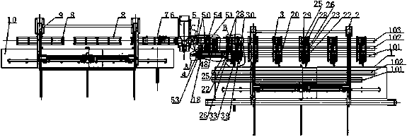
[0061] (1), place the U-shaped longitudinal beam 102 and the lining beam 101 on the feeding platform 1 respectively, for standby;

[0062] (2) Use the feeding extraction device 2 to suck and lift the spare U-shaped stringer 102 , and lift the U-shaped stringer 102 with the opening upward directly to the stringer feed roller 25 and the stringer feed roller 48 . For the U-shaped longitudinal beam 102 with the opening downward, it is lifted to the automatic turning device 20 first, and the automatic turning device 20 turns it over 180°, and pulls it to the lining beam feeding roller 22 through the lining beam side pulling cylinder 21 , and then use the feed extract...


PUM


Abstract

The invention relates to a production device and a machining method for U-shaped longitudinal beam and lining beam automatic positioning beam combining spot welding. The production device and the machining method are characterized in that a beam combining feedstock feeding device is placed on the right side of an automatic spot welding device, a lining beam end face positioning component is placed on the front side of the beam combining feedstock feeding device, six sets of longitudinal beam feeding devices are sequentially arranged on the right side of the beam combining feedstock feeding device and the right side of the lining beam end face positioning component, and a feeding platform is placed in front of the longitudinal beam feeding devices. A feedstock extraction device is placed at back of the longitudinal beam feeding devices, and a track installed in the feedstock extraction device forwards extends to reach the position above the feeding platform. A beam combining discharged material feeding device and two sets of discharged material supporting rollers are sequentially placed on the left side of the automatic spot welding device. A discharging platform is placed in front of the beam combining discharged material feeding device and the discharged material supporting rollers, a discharged material extraction device is placed at back of the beam combining discharged material feeding device and the discharged material supporting rollers, and a track installed in the discharged material extraction device forwards extends to reach the position above the discharging platform.

Description

technical field [0001] The invention relates to the field of U-shaped longitudinal beams and their lining beam positioning, beam closing and spot welding technology, in particular to a U-shaped longitudinal beam with automatic positioning and its lining beam automatic beam closing and spot welding production equipment. Background technique [0002] At present, in the field of technology used for U-shaped longitudinal beam and its lining beam positioning, beam closing, and spot welding, manufacturers all adopt manual positioning, beam closing, manual spot welding or automatic spot welding. The equipment used in these two production processes has problems such as low productivity and complicated process. The existing "U"-shaped longitudinal beams and their lining beam positioning, beam closing, and spot welding processes use manual handling and turning during the handling or turning of the "U"-shaped longitudinal beams and their lining beams, and the handling and turning eff...

Claims


Application Information

Patent Timeline
IPC IPC(8): B23K31/02B23K37/047B23K37/00
Inventor 赵加蓉李耶夫江涛
Owner 广州市力鼎汽车零部件有限公司
Why Eureka
Try Eureka