
Wheel positioner for tire building machine

A steel ring positioner and tire building machine technology, applied in the field of tire manufacturing, can solve the problems of increased maintenance time, affecting tire quality, high maintenance frequency, etc., to improve tire quality, reduce maintenance time and frequency, and improve production efficiency Effect

Active Publication Date: 2015-11-18
JIANGSU GENERAL SCI TECH
View PDF3 Cites 0 Cited by
  • Summary
  • Abstract
  • Description
  • Claims
  • Application Information

AI Technical Summary

Problems solved by technology

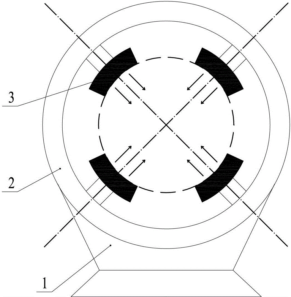
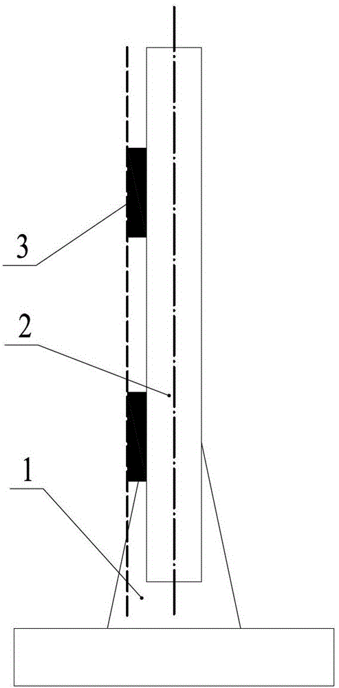
[0004] In order to ensure the positioning accuracy, the sides of the positioning block 3 on the four steel ring positioners are preferably guaranteed to be on a plane ( figure 2 As shown), since the guide rail guide in the existing steel ring positioner is the pulley 9, the gap between the pulley 9 and the guide rail 7 is relatively large, so that the guide rail 7 will shake up and down during the forward and backward movement, and the four positioning blocks 3 cannot be guaranteed. The side of the tire is on the same plane, which causes the positioning of the steel ring to change, which affects the quality of the tire. It needs to be adjusted frequently, and the adjustment must be adjusted with the help of measuring tools. The maintenance time is increased, the maintenance frequency is high, and the production efficiency is low.

Method used


Image

  • Wheel positioner for tire building machine
  • Wheel positioner for tire building machine
  • Wheel positioner for tire building machine

Examples


Embodiment Construction

[0014] The present invention will be further described below in conjunction with specific drawings and embodiments.

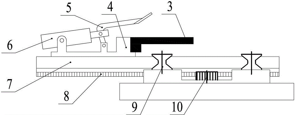
[0015] As shown in the figure: the rim positioner of the tire building machine in the embodiment is mainly composed of a positioning block 3, a connecting seat 4, a guide rail 7, a guide rail guide and a guide rail driving mechanism. The positioning block 3 is installed on the connecting seat 4. The connecting seat 4 is installed on the guide rail 7, and the guide rail 7 is movably arranged in the guide rail guide, and the guide rail 7 is driven by the guide rail drive mechanism to move in the guide rail guide; the guide rail guide adopts a slide block 11, and the slide block 11 is provided with The chute adapted to the shape of the lower part of the guide rail 7, the lower part of the guide rail 7 is placed in the chute and can slide relatively.

[0016] Compared image 3 , Figure 4 It can be seen that the main purpose of the present invention is to replace...


PUM


Abstract

The invention relates to a steel ring positioner for a tire building machine. The positioner comprises a positioning block, a connecting seat, a guide rail, a guide rail guiding element and a guide rail driving mechanism, wherein the positioning block is arranged on the connecting seat, the connecting seat is mounted on the guide rail, and the guide rail is movably installed in the guide rail guiding element and moves in the guide rail guiding element under the driven by the guide rail driving mechanism. The positioner is characterized in that the guide rail guiding element employs a sliding block, the sliding block is provided with a sliding chute with a shape matching with the shape of the bottom of the guide rail and the bottom of the guide rail is placed in the sliding chute and can slide relative to the sliding chute. According to the invention, the steel ring positioner has a simple and ingenious structure; the guide rail guiding element in the steel ring positioner is changed from a conventional pulley into the sliding block, so steel ring positioning is more accurate, which is favorable for improvement of tire quality; a reconstruction scheme in the invention is easy, and investment of considerable capital and modification of equipment are not needed; a production process for a reconstructed steel ring positioner remains unchanged, maintenance time and maintenance frequency are reduced, and production efficiency is improved.

Description

technical field [0001] The invention relates to a steel ring positioner used on a tire building machine, belonging to the technical field of tire manufacturing. Background technique [0002] Existing wheeled vehicles, especially large freight vehicles, run on the expressway, not only require a higher speed but also require a better load-bearing capacity, wherein the high load-bearing capacity puts forward more challenges to the tire bead structure of the load-carrying vehicle. high demands. [0003] In order to meet these high requirements, high-precision manufacturing equipment is required in the tire bead manufacturing process to ensure the positioning accuracy of the steel ring in the tire bead structure. In the prior art, the steel ring positioner on the tire building machine is a group of four ( figure 1 shown), installed on the ring fixing frame 2 of the positioning bracket 1. Each rim positioner includes a positioning block 3, a connecting seat 4, a guide rail 7, a...

Claims


Application Information

Patent Timeline
Patent Type & Authority Patents(China)
IPC IPC(8): B29D30/48
Inventor 陈敬
Owner JIANGSU GENERAL SCI TECH
Learn More