Rear force transmission structure of automobile

A kind of technology of automobile rear and force transmission beam

Active Publication Date: 2013-09-25
GREAT WALL MOTOR CO LTD
View PDF2 Cites 4 Cited by
  • Summary
  • Abstract
  • Description
  • Claims
  • Application Information

AI Technical Summary

Problems solved by technology

[0006] 3. When the vehicle has a side collision, the side collision force directly acts on the rear side wall assembly, and is transmitted to the single-channel force beam 3 through the C-pillar 2, and the impact force on the single-channel force beam 3 is relatively large; At the same time, th

Method used


Image

  • Rear force transmission structure of automobile
  • Rear force transmission structure of automobile
  • Rear force transmission structure of automobile

Examples


Embodiment Construction

[0025] The specific implementation manners of the present invention will be further described in detail below in conjunction with the accompanying drawings and embodiments. The following examples are used to illustrate the present invention, but are not intended to limit the scope of the present invention.

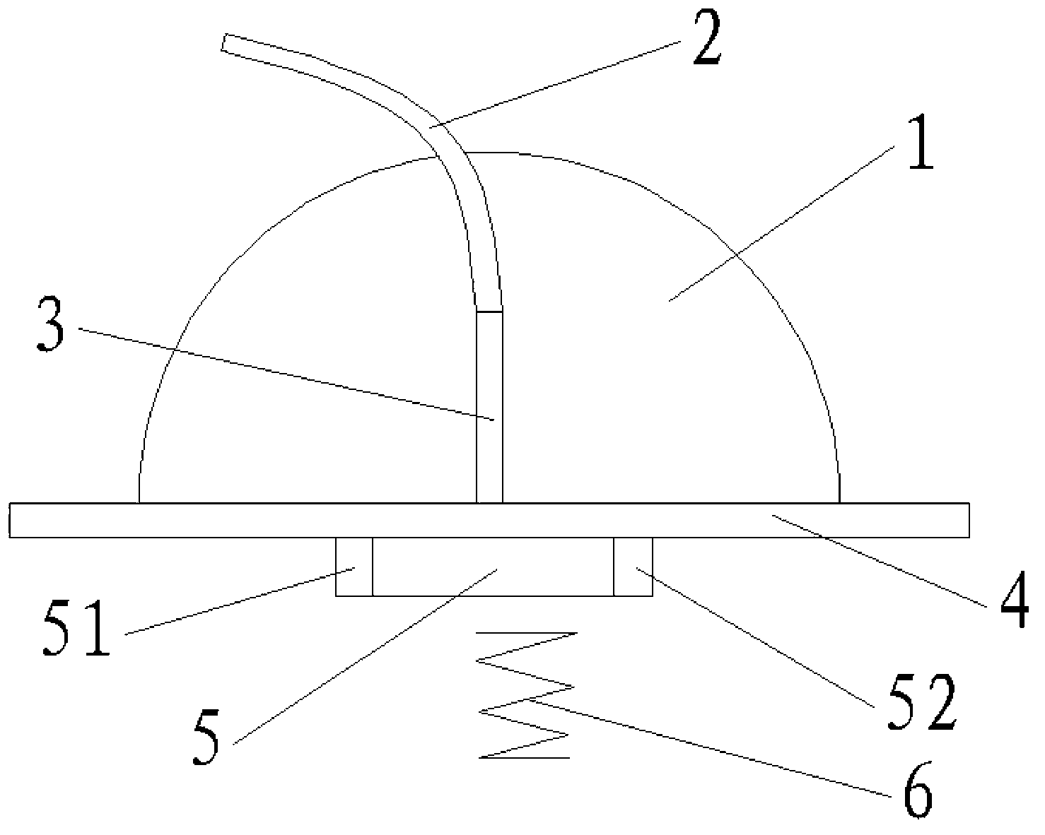
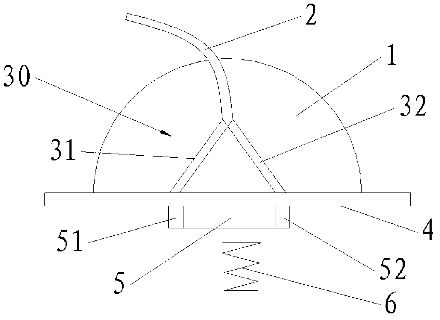
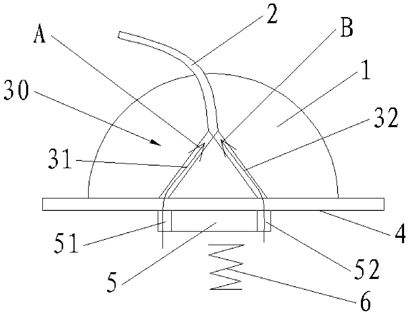
[0026] The "first" and "second" mentioned in this document are for the convenience of explanation and to make the expression clearer. In fact, there is no primary and secondary relationship, and they cannot be understood as restrictions on dowel bars and rear floor beams. Arrows A, B, C, D, E and F in the accompanying drawings of the description are not the invention structure of the rear portion of the present invention's power transmission structure itself, and are not used to limit the present invention, and are only used to represent the impact of the automobile under various working conditions. The direction of force transmission.

[0027] Such as figure 2 As shown...


PUM


Abstract

The invention relates to the field of automobiles, and discloses a rear force transmission structure of an automobile. The rear force transmission structure comprises a longitudinal floor beam, a force transmission beam and a column C; the longitudinal floor beam is connected with a shock absorber; one end of the column C is connected with an automobile body, the other end of the column C is connected with the longitudinal floor beam by the force transmission beam, and the force transmission beam is connected with a rear wheel cover; the force transmission beam comprises a first force transmission rod and a force transmission rod. Parts of longitudinal force are transmitted by the first force transmission rod and the second force transmission rod respectively, the strength of impact on a part, which is connected with the force transmission beam, of the rear wheel cover is reduced, and accordingly the rear wheel cover is protected. The rear force transmission structure has the advantages that the first force transmission rod and the second force transmission rod are arranged in a splay manner, and a hollow triangular structure is formed between the force transmission beam and the longitudinal floor beam, so that the stability of the force transmission beam is improved, and the rigidity of the rear wheel cover is further improved; the triangular structure is favorable for improving the ability of transmitting rear collision force to the automobile body via the force transmission beam and the column C after rear collision of the automobile occurs; the force transmission beam is connected with two rear transverse floor beams, and accordingly energy of lateral collision force can be advantageously absorbed by the automobile.

Description

technical field [0001] The invention relates to the field of automobiles, in particular to an automobile rear force transmission structure. Background technique [0002] The rear structure of the car includes the rear floor assembly, the rear side wall assembly and the rear wheel housing. The rear floor assembly includes floor longitudinal beams and rear floor cross beams, and the floor longitudinal beams are connected to the shock absorbers through shock absorber supports; the rear side wall assembly includes C pillars, one end of which is connected to the roof cross beams of the vehicle body, and the other One end is connected to the floor longitudinal beam through the force transmission beam; the rear wheel cover is used as the connection carrier of the force transmission beam and connected to the force transmission beam. [0003] Such as figure 1 As shown, the partial schematic diagram of the existing rear structure of the automobile, during the running of the automobi...

Claims


Application Information

Patent Timeline
IPC IPC(8): B62D25/08B60R19/02
Inventor 黄勇申力伟高庆林贺志杰阎延鹏许明王超卢曦
Owner GREAT WALL MOTOR CO LTD
Why Eureka
Try Eureka