Knitwear rolling and inspecting machine

A technology of material rolling and machine inspection, which is applied in the directions of winding strips, thin material processing, transportation and packaging, etc. It can solve the problems of difficulty in ensuring the quality of rope-shaped curling, stripping and flattening, affecting the production process, and waste of fabrics, etc., to achieve The effect of saving manpower input and reducing work intensity

Inactive Publication Date: 2013-09-25
常熟市龙略机电有限公司
View PDF9 Cites 14 Cited by
  • Summary
  • Abstract
  • Description
  • Claims
  • Application Information

AI Technical Summary

Problems solved by technology

[0004] Although the above-mentioned technical solutions that are not limited to examples have corresponding achievements, they have the following advantages and disadvantages: one is that there are curling edges on both sides of the length direction of the knitted fabric after the previous process such as the shaping process. Therefore, in the process of rolling into a roll by the rolling inspection machine, because the curling cannot be flattened, it can only be wound with the knitted fabric in a superimposed state or a folded state, commonly known as rope-shaped curling, so it affects the needle. The roll quality of textiles is specifically manifested in the fact that in the process of fabric manufacturers processing clothing and bedding products, it is necessary to pre-level the edges of the unexpanded fabrics on the self-cloth rolls, that is, the rope-like parts, and most of them use edge trimming machines. (also known as trimming machine) to cut the curling or ironing, which will cause waste of

Method used


Image

  • Knitwear rolling and inspecting machine
  • Knitwear rolling and inspecting machine
  • Knitwear rolling and inspecting machine

Examples


Example Embodiment

[0022] Example:

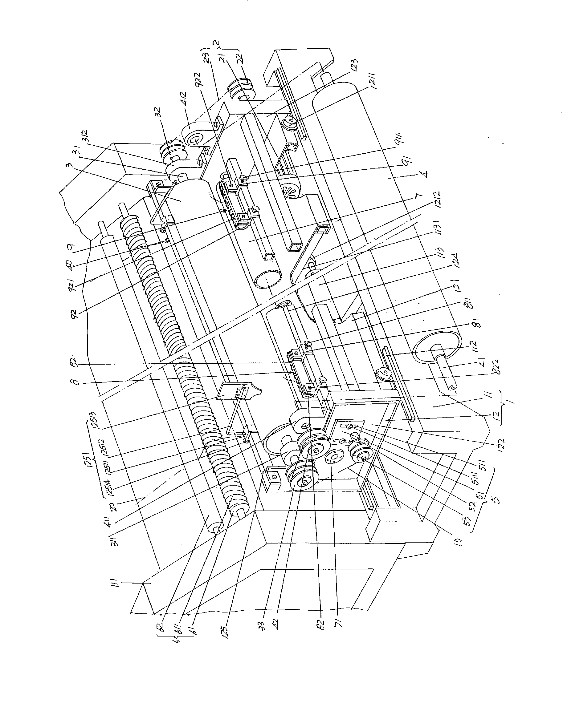
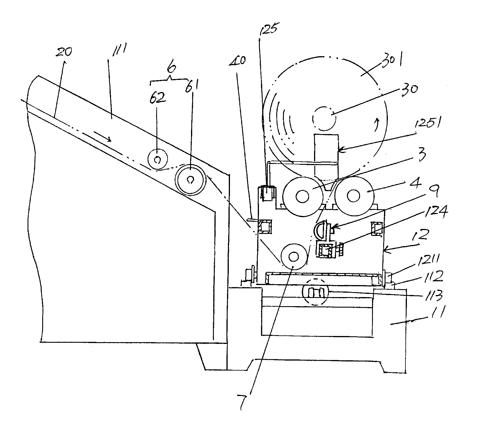
[0023] See figure 1 , a cloth roll frame 1 is given, the cloth roll frame 1 includes a base 11 and a mobile trolley 12, the base 11 is arranged on the floor of the use place, and a lengthwise direction of the base 11 is provided. side ie figure 1 A cloth guide mechanism bracket 111 is fixed on the rear side of the shown position, and a guide rail 112 is fixed on the upper part of the corresponding two sides of the base 11 in the longitudinal direction. ground on the guide rail 112 . In order to avoid unnecessary waste of materials, since the left and right movement ranges of the mobile trolley 12 on the base 11 are small, only a section of guide rails are fixed at both ends of the upper part of the corresponding two sides of the base 11 in the length direction. 112.

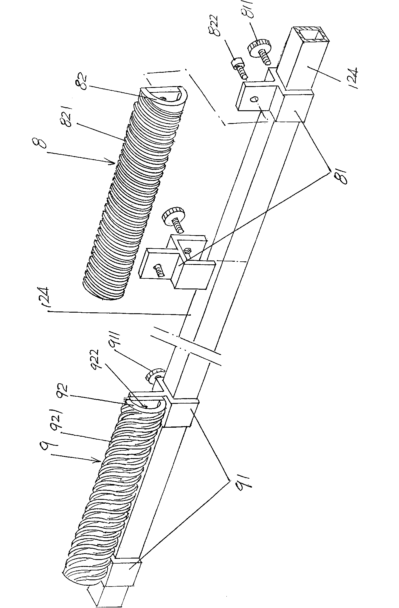
[0024] The aforementioned mobile trolley 12 includes a trolley base 121, left and right wall panels 122, 123, and a fixing rod 124 for the stripping mechanism. 122 is fixed on the left end ...


PUM


Abstract

The invention belongs to the technical field of knitting machinery and discloses a knitwear rolling and inspecting machine which comprises a cloth rolling rack, a power transmission mechanism, a driving cloth roller, a driven cloth roller, a transition transmission belt, a cloth guiding mechanism and a cloth guiding roller. A driving cloth roller driving wheel and a driving cloth roller transition wheel are fixed at the right end and the left end of a driving cloth roller shaft respectively, and a driven cloth roller transmission wheel is fixed at the left end of a driven cloth roller shaft. The knitwear rolling and inspecting machine is characterized in that the machine further comprises a left edge-peeling and cloth-propping mechanism and a right edge-peeling and cloth-propping mechanism, the left edge-peeling and cloth-propping mechanism is fixed at the left end of the cloth rolling rack and corresponding to the lower portion between the driving cloth roller and the driven cloth roller, and the right edge-peeling and cloth-propping mechanism is fixed at the right end of the cloth rolling rack and corresponding to the lower portion between the driving cloth roller and the driven cloth roller. By the knitwear rolling and inspecting machine, the end face of a cloth roll can be enabled to be flush, formed roll-shaped knitwear can be high in rolling quality, operating intensity of workers can be reduced, manpower input can be saved, and influences of changing of human factors can be avoided.

Description

technical field [0001] The invention belongs to the technical field of knitting and textile machinery, and in particular relates to a knitting fabric rolling inspection machine. Background technique [0002] The knitted fabric rolling inspection machine is also called the fabric rolling inspection machine, and then referred to as the rolling inspection machine. The reason why it is named the rolling inspection machine is because it has dual functions or double functions. The shaped fabric is formed into rolls for storage, transportation and management, etc.; the second is to check and accept the fabric to prevent defective products from entering the market. More precisely, when the roll-inspecting machine winds up the finished fabric from the sizing machine into a cylindrical body, the online operator observes the condition of the fabric. Usually, the roll inspection machine is also equipped with a meter counting device (also called a length counting device) to record the...

Claims


Application Information

Patent Timeline
IPC IPC(8): B65H23/34B65H18/20
Inventor 潘熠潘慧潘沁
Owner 常熟市龙略机电有限公司
Why Eureka
Try Eureka