Variable valve train for an internal combustion engine

A technology of valve mechanism and internal combustion engine, applied in the direction of internal combustion piston engine, combustion engine, machine/engine, etc., to achieve the effect of low cost and installation consumption, and minimized lever mass

Inactive Publication Date: 2013-09-25
SCHAEFFLER TECH AG & CO KG
View PDF6 Cites 4 Cited by
  • Summary
  • Abstract
  • Description
  • Claims
  • Application Information

AI Technical Summary

Problems solved by technology

The disadvantage is that with this valve train no additional valve travel can b...

Method used


Image

  • Variable valve train for an internal combustion engine
  • Variable valve train for an internal combustion engine
  • Variable valve train for an internal combustion engine

Examples


Embodiment Construction

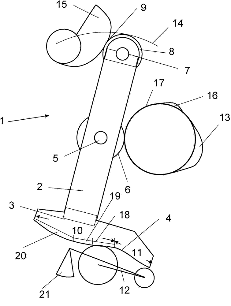
[0013] figure 1 A fully variable valve train 1 of an internal combustion engine is shown, which is equivalent to a BMW electronic valve control system in terms of basic structure and function.

[0014] The valve train 1 is formed by an elongated rocker 2 . The elongated rocker 2 has at the lower end 3 a transfer surface 4 integrally coupled, which consists of a zero-travel track 10 and a travel track 11 following the zero-travel track in the pivoting direction of the lever, and which The surface 4 is in contact with the valve opener 12 , which is present as a rocker arm and rests in its region shown here on the right on a support element, not shown.

[0015] Viewed from the stroke track 11, the aforementioned zero-stroke track 10 has successively a connection zero-stroke section 18, a cut-off zero-stroke section 19 and a remaining zero-stroke section 20, wherein, according to figure 1 The zero stroke section 18 is in contact with the valve opener 12 when it is turned on.

...


PUM


Abstract

The invention provides a variable valve train for an internal combustion engine. The variable lift valve train for the internal combustion engine with internal combustion, comprises a pivoted lever including a transmission surface on one end, a counter running surface in a central region and, on a further end, a support element and a contact element, said transmission surface comprising a zero lift path and, adjoining said zero lift path in a lever pivoting direction, a lift path, said transmission surface being in contact with a valve opener, said counter running surface being loaded by at least one lift cam, said support element being guided on a lever guide path, and said contact element, for adjusting a valve lift being loaded by an adjusting device in direction of said lever guide path, and directly in a region of the pivoted lever, an effective and optionally additionally actuable element for creating an additional valve lift during a base circle phase of the lift cam.

Description

technical field [0001] Valve train with variable stroke for an internal combustion engine with internal combustion, having a rocker with a transfer surface at one end, a mating surface in a central region and a support device and a contact at the other end device, the transmission surface is composed of a zero-stroke track and a stroke track following the zero-stroke track in the pivoting direction of the rod, and is in contact with the valve opener, and the mating surface is loaded by at least one stroke cam, wherein the supporting device is on the chute track The upper guide, and wherein the contact device is acted upon by the adjusting device in the direction of the link rail for adjusting the valve stroke. Background technique [0002] This valve train is in DE 102 35 402 A1 figure 1 It is shown in , and is used by BMW under the term "Valvetronic" as a full stroke variable valve control device. A disadvantage is that with this valve train no additional valve travel can...

Claims


Application Information

Patent Timeline
IPC IPC(8): F01L13/00
CPCF01L1/34F01L2820/032F02D13/0273F02D2041/001F02M26/01Y02T10/12
Inventor 沃尔夫冈·克里斯特根迈克尔·舍贝尔
Owner SCHAEFFLER TECH AG & CO KG
Why Eureka
Try Eureka