Composite lamination type light hub
A composite material and laminated technology, which is applied in chemical instruments and methods, wind turbine components, wind engines, etc., can solve the problems of heavy structure, complicated process, and affecting the price of hubs, and achieve good damping characteristics and low maintenance costs. , light weight effect
Inactive Publication Date: 2013-09-25
沈阳风电设备发展有限责任公司
View PDF5 Cites 0 Cited by
- Summary
- Abstract
- Description
- Claims
- Application Information
AI Technical Summary
Problems solved by technology
The process is complicated, the structure is heavy, and if there is a problem, it can only be replaced but not repaired. This is the disadvantage of the traditional wheel hub, which affects the price of the wheel hub, and affects the starting operation of the rotating parts and the quick response ability of re-acceleration.
Method used
View moreImage
Smart ImageViewing Examples
Examples
Embodiment
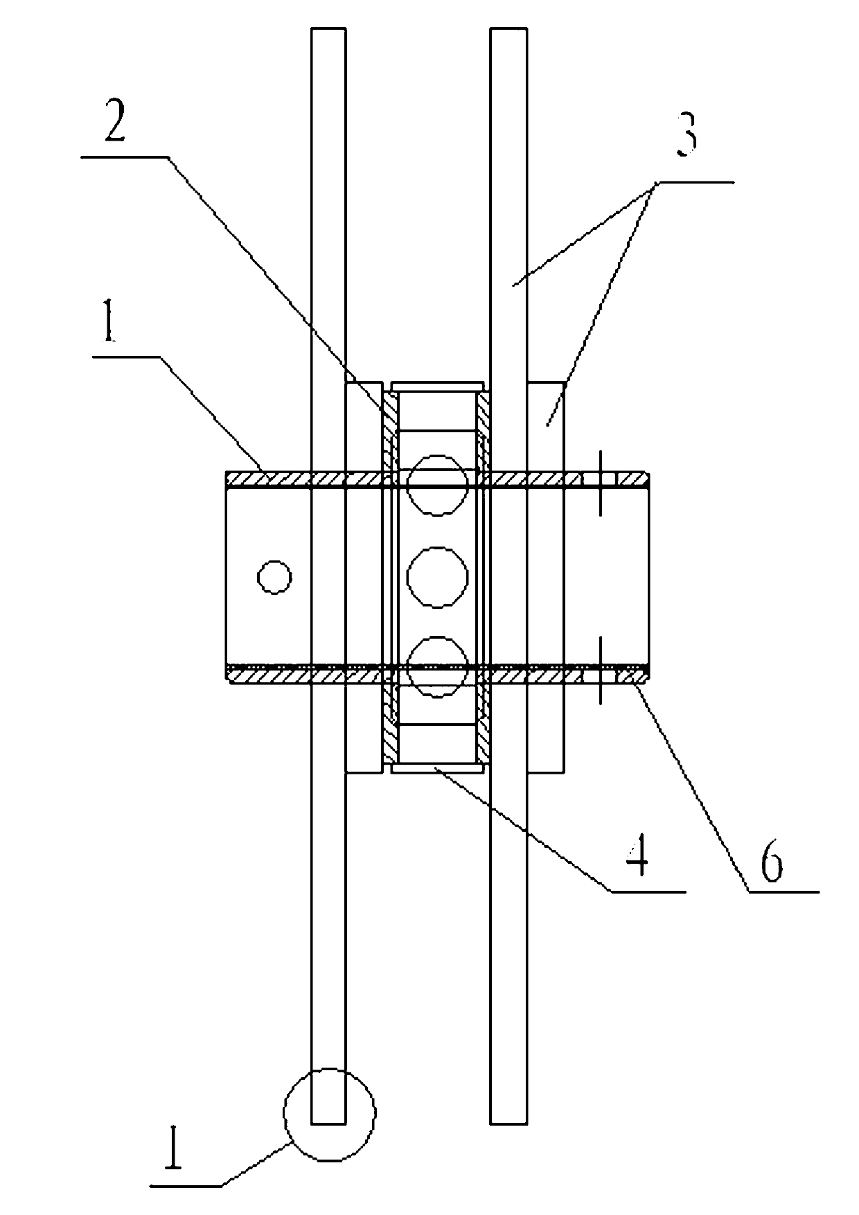
[0017] Figure 5 As shown, in this example, the composite material laminated lightweight hub is applied to the blade impeller of wind power generation, and the composite material lamination group 3 on the hub core is fixedly connected to the blade impeller 9, and then the hub core is installed on the generator On the shaft, it becomes a lightweight wind turbine.
Login to View More PUM
 Abstract
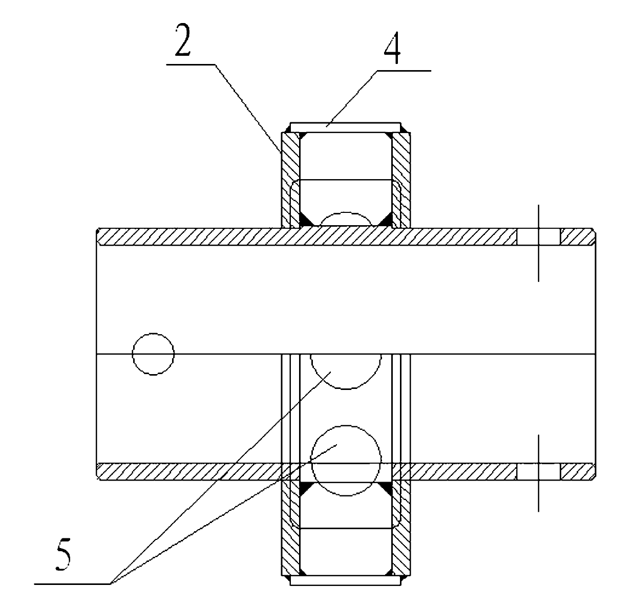
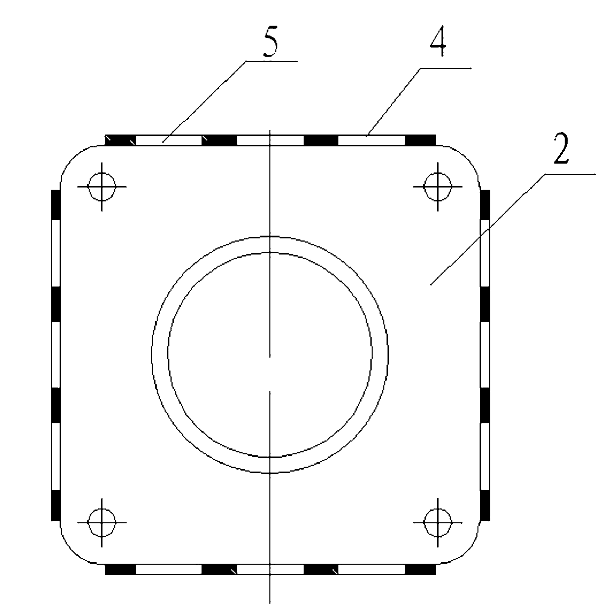
A composite lamination type light hub comprises a hub weld part and multiple groups of composite laminations, wherein the hub weld part is formed by welding a hub core, hub core clamp plates and hub core reinforced support plates, the two hub core clamp plates are mounted in a sleeving manner and fixedly welded on two sides of a locating shaft shoulder of the hub core, and the hub core reinforced support plates are welded on the periphery. Each group of composite laminations comprises two metal plates internally clamped with multilayer composite laminations, and the multiple groups of composite laminations are mounted on the hub core in a sleeving manner, placed on two sides of each hub core clamp plate and fixed on the hub core clamp plates. The composite lamination type light hub adopts metal plate hollowed-out structure and an advanced composite material structure to achieve a light hub with a brand new conception, is mainly used for energy collection and energy output, has the advantages of light weight, high intensity, high reliability, fatigue resistance, easiness in maintenance, energy conservation and environmental protection, as well as the advantages of good damping characteristic, capacity of attenuation vibration and low maintenance cost.
Description
technical field [0001] The invention relates to a wheel hub installed with a transmission shaft or a drive shaft, in particular to a composite material laminated lightweight wheel hub. Background technique [0002] With the development of science and social progress, low-carbon environmental protection has become the main theme of the times. The application of new technologies, new processes, and new materials, low cost, low energy consumption, and low pollution, and the realization of lightweight product components meet the needs of the company's own development. Corporate social obligations and responsibilities. Lightweight hubs are an important part of light-weight running machinery. Lightweight hubs can effectively reduce vibration transmission, reduce rotational inertia, reduce running resistance, and make equipment run smoothly. The process is complicated, the structure is heavy, and if there is a problem, it can only be replaced but not repaired. This is ...
Claims
Login to View More Application Information
Patent Timeline
 Patent Type & Authority Applications(China)
IPC IPC(8): F03D11/00B32B15/04
Inventor 戴峥峥金长鑫
Owner 沈阳风电设备发展有限责任公司
Features
- R&D
- Intellectual Property
- Life Sciences
- Materials
- Tech Scout
- Unparalleled Data Quality
- Higher Quality Content
- 60% Fewer Hallucinations
Learn More Browse by: Latest US Patents, China's latest patents, Technical Efficacy Thesaurus, Application Domain, Technology Topic, Popular Technical Reports.
© 2025 PatSnap. All rights reserved.Legal|Privacy policy|Modern Slavery Act Transparency Statement|Sitemap|About US| Contact US: help@patsnap.com


