Inlaid valve element and manufacturing process thereof

An inlaid and spool technology, which is applied in the direction of manufacturing tools, cores, valve devices, etc., can solve the problems of increased resistance to the up and down movement of the spool, poor precision of the chute, rough surface, etc., to save production costs and service life Good effect of improving and anti-friction performance

Active Publication Date: 2013-09-25
WUHU JINMAO FLUID TECH CO LTD
View PDF6 Cites 1 Cited by
  • Summary
  • Abstract
  • Description
  • Claims
  • Application Information

AI Technical Summary

Problems solved by technology

[0003] The spool made directly by this process, the spool chute on the spool is formed by one-time casting, and the production efficiency is high. However, due to the direct casting, the chute has poor precision and rough surface, which causes the resistance of the spool to move up and down to increase. When the valve core is covered with rubber, the product is unqualified due to the deviation of the thickness of the rubber on both sides of the valve core

Method used


Image

  • Inlaid valve element and manufacturing process thereof
  • Inlaid valve element and manufacturing process thereof
  • Inlaid valve element and manufacturing process thereof

Examples


Embodiment Construction

[0034] In order to further explain the technical means and effects of the present invention to achieve the intended purpose of the invention, the specific implementation, structure, features and effects of the present invention will be described in detail below in conjunction with the accompanying drawings and preferred embodiments. rear.

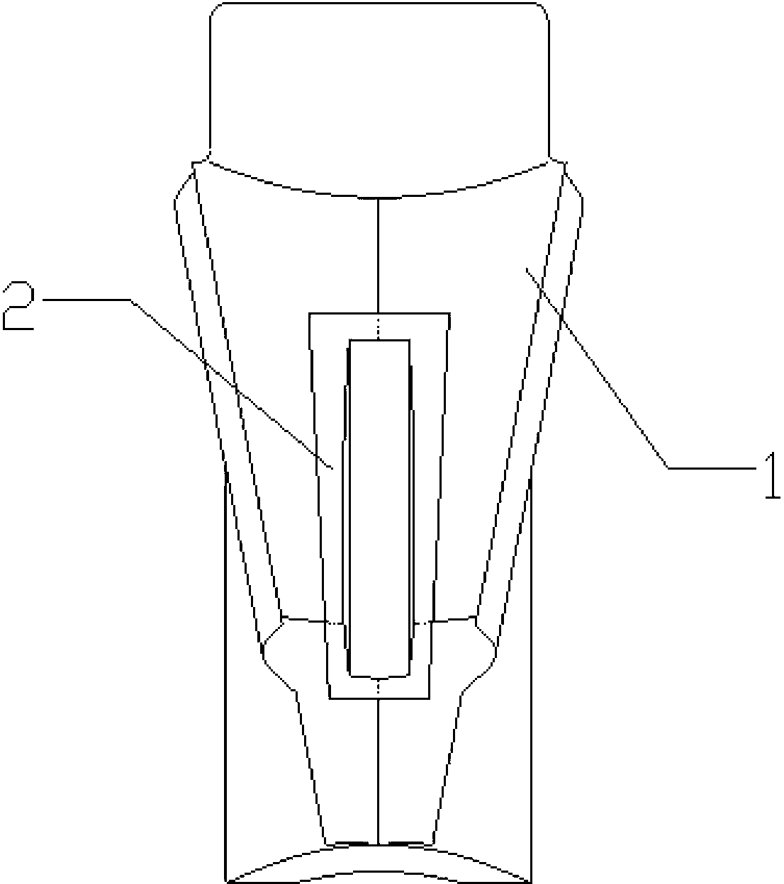
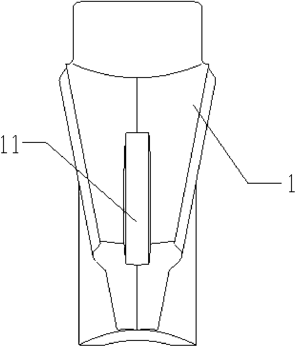
[0035] Such as figure 1 , a mosaic type spool, including a spool body 1, and a spool chute protection sleeve 2, the two sides of the spool body 1 are respectively provided with an inlay groove 11 for installing the spool chute protection sleeve 2.

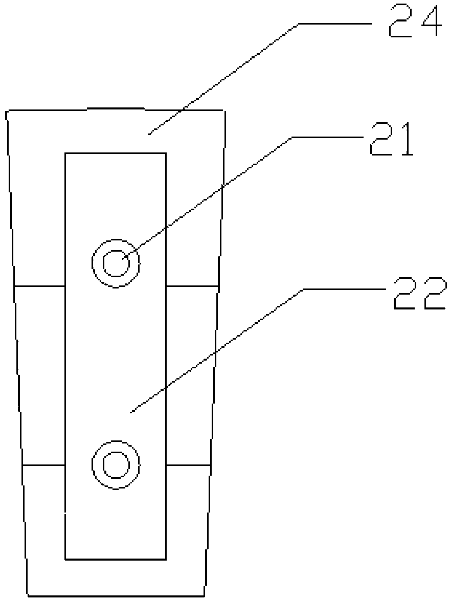
[0036] Such as figure 2 , image 3 , Figure 4 , Figure 5 As shown, the spool chute protective sleeve 2 includes an inlaid baffle 24, and a positioning groove 22 is arranged in the inlaid baffle 24, and a plurality of positioning holes 21 are arranged in the locating groove 22; the spool chute protective sleeve 2 is installed in the inlaid groove 11 After that, they are fixed to each othe...


PUM


Abstract

The invention relates to an inlaid valve element and a manufacturing process thereof. The inlaid valve element comprises a valve element body and valve element slide groove protecting sleeves. The two sides of the valve element body are respectively provided with an inlaid groove used for installing the valve element slide groove protecting sleeves which comprise inlaid baffles. A locating groove is formed in each inlaid baffle. A plurality of locating holes are formed in each locating groove. The valve element slide groove protecting sleeves are installed in the inlaid grooves and mutually fixed through rubber coating. Due to the fact that the valve element slide groove protecting sleeves are made of high-temperature and wear resistant plastic parts, the wear resistance is good, and the service life of the valve element is prolonged. Due to the fact that the two sides of the valve element are inlaid with the valve element slide groove protecting sleeves, on one hand, the weight of the valve element is reduced, and on the other hand, production cost is saved.

Description

technical field [0001] The invention relates to an inlaid valve core and its manufacturing process. Background technique [0002] The manufacturing process of the original valve core includes: manufacturing the core box mold of the valve core and the shell mold of the valve core, both of which are mold-covered sand molds; using the mold of the left core box of the valve core and the mold of the right core box of the valve core to form the core of the valve core Cavity, which is used to make the core of the valve core; use the mold of the left shell of the valve core and the mold of the right shell of the valve core to form the left and right shells of the valve core; put the prepared core of the valve core into the left shell of the valve core, and then close it The housing of the right spool is molded to form a spool cavity; the box is closed, poured, and post-processed to form a finished spool made of ductile iron. [0003] The spool made directly by this process, the spo...

Claims


Application Information

Patent Timeline
Patent Type & Authority Applications(China)
IPC IPC(8): F16K51/00B22C9/02B22C9/10
Inventor 孙述全
Owner WUHU JINMAO FLUID TECH CO LTD
Why Eureka
Try Eureka