A New Linear Electric Loading System
What is Al technical title?
Al technical title is built by PatSnap Al team. It summarizes the technical point description of the patent document.
A linear motor and linear technology, applied in the testing of machines/structural components, measuring devices, instruments, etc., can solve the problems of large connection gap, poor dynamic performance, long loading reverse time, etc., achieve high loading accuracy and improve dynamic performance, eliminating the effect of long reverse times
Inactive Publication Date: 2016-03-02
BEIHANG UNIV
View PDF4 Cites 2 Cited by
Summary
Abstract
Description
Claims
Application Information
AI Technical Summary
This helps you quickly interpret patents by identifying the three key elements:
Problems solved by technology
Method used
Benefits of technology
Problems solved by technology
[0005] The purpose of this invention is to solve the problems of the existing linear electric loading table structure, such as large connection gap, poor dynamic performance and long loading reverse time, etc., and propose a new type of linear electric loading system, which can effectively control the existing Various specifications of linear steering gear apply various forms of loads to meet the needs of simulation
Method used
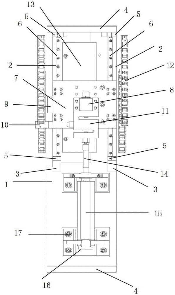
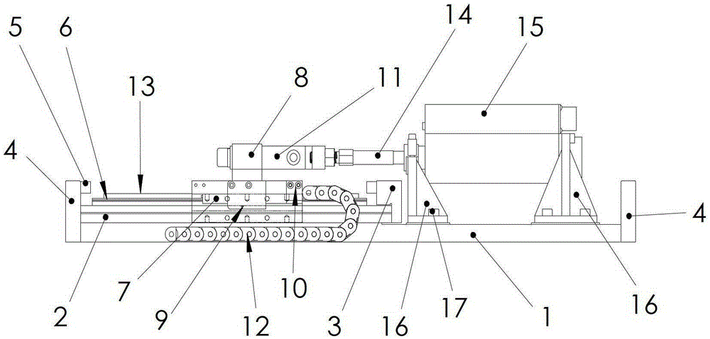
Image
Click on the blue label to locate the original text in one second.
Reading with bidirectional positioning of images and text.
Examples
Embodiment Construction
[0036] The present invention will be further described in detail with reference to the accompanying drawings and embodiments.
[0037] The present invention is a novel linear electric loading system, such as figure 1 , figure 2 As shown, it includes bottom plate 1, bottom plate boss 2, anti-collision block installation platform 3, anti-collision block 4, rubber block 5, guide rail 6, sliding platform 7, connecting block 8, magnetic scale 9, drag chain installation angle iron 10 , force sensor 11, drag chain 12, linear motor 13, threaded connecting rod 14, linear steering gear 15, support plate 16, fixing screw 17.
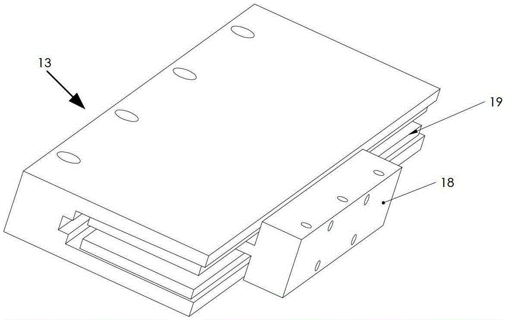
[0038] Linear motor 13 such as image 3 As shown, a motor coil 18 and a permanent magnet 19 are included.
[0039] The bottom plate 1 is rectangular, and anti-collision blocks 4 are respectively installed on the two wide sides of the rectangle, and the anti-collision block 4 and the bottom plate 1 are fixed by hexagon socket head screws.
[0040] An anti-colli...
PUM
Abstract
The invention discloses a novel linear electric loading system. The novel linear electric loading system comprises a base plate, base plate bosses, bumper block installing tables, bumper blocks, rubber blocks, guide rails, a slide platform, a connecting block, a magnetic railing ruler, drag chain installing angle iron, a force sensor, drag chains, a linear motor, a threaded connecting rod, a linear steering engine, a supporting plate and fixing screws. According to the novel linear electric loading system, aluminum alloy platforms are adopted in the linear motor, the guide rails and the like, and therefore dynamic performance of the system can be improved beneficially. Compared with a traditional loading structure that a servo motor is installed with a ball screw, the novel linear electric loading system has the advantages that the slide platform is adopted, a loading motor and the steering engine are connected through threaded rods, and the shortcomings that the traditional loading structure is long in reversed time and poor in dynamic performance are effectively overcome. Compared with a traditional connecting method using lug rings, the method of connecting the loading motor and the electric steering engine through the threaded rods avoids connecting gaps and improves loading accuracy. When the loading system breaks down, the phenomenon of rotation blocking of the steering engine can be prevented, the steering engine can not be damaged, and the effect of safety protection is achieved.
Description
technical field [0001] The invention relates to a novel linear electric loading system, which belongs to the technical field of control devices, in particular to a loading table of the electric loading system of a linear steering gear. Background technique [0002] The electric steering gear is a classic actuator in the aerospace field, which is of great significance to the normal flight and maneuver control of the aircraft, and is an important flight control servo component. In order to verify the design of the electric steering gear and ensure the quality of the product before leaving the factory, it is necessary to carry out the load test of the electric steering gear. As a new type of power-by-wire actuator, the linear steering gear has broad application prospects. It can be used not only in the flight control system, but also in other occasions that require actuation on the aircraft. [0003] In order to ensure the quality of the research and development of the linear ...
Claims
Application Information
Patent Timeline
Application Date:The date an application was filed.
Publication Date:The date a patent or application was officially published.
First Publication Date:The earliest publication date of a patent with the same application number.
Issue Date:Publication date of the patent grant document.
PCT Entry Date:The Entry date of PCT National Phase.
Estimated Expiry Date:The statutory expiry date of a patent right according to the Patent Law, and it is the longest term of protection that the patent right can achieve without the termination of the patent right due to other reasons(Term extension factor has been taken into account ).
Invalid Date:Actual expiry date is based on effective date or publication date of legal transaction data of invalid patent.