Ion source device and ion beam generating method

An ion beam and ion source technology, which is applied in the direction of ion beam tubes, discharge tubes, electrical components, etc., can solve the problems of shortening and increasing the life of the cathode 22, and achieve the effect of increasing the beam current.

Active Publication Date: 2013-09-25
SENCORP
View PDF6 Cites 6 Cited by
  • Summary
  • Abstract
  • Description
  • Claims
  • Application Information

AI Technical Summary

Problems solved by technology

At this time, it is conceivable that since the plasma density in the cathode 22 and the repeller 23 also becomes high, problems such as shortening the lifetime of the cathode 22 occur.

Method used


Image

  • Ion source device and ion beam generating method
  • Ion source device and ion beam generating method
  • Ion source device and ion beam generating method

Examples


Embodiment Construction

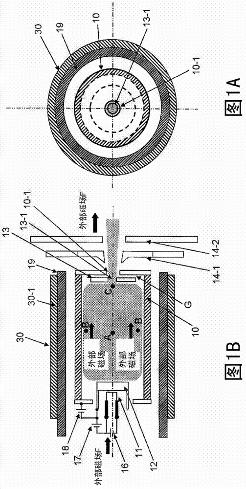
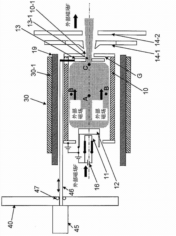
[0028] An embodiment of an ion source device according to the present invention will be described with reference to FIG. 1 . Figure 1A It is a front view of the ion source device viewed from the extraction part side of the ion beam, but it is assumed that the Figure 1B The state of the suppression electrode 14-1 and the ground electrode 14-2 is shown as observed.

[0029] [structure]

[0030] In FIG. 1 , the ion source device includes an arc chamber 10 having a space for forming plasma. The arc chamber 10 has a cylindrical shape. Here, the cylindrical arc chamber 10 is placed horizontally to form an electron source on one end side (back side) in the direction of the central axis. Like the electron source described in FIG. 3 , the electron source in this ion source device also includes a filament 11 and a cathode 12 . The cathode 12 emits thermal electrons for generating beam electrons that ionize neutral molecules from its thermal electron emitting surface. A reflector 1...


PUM


Abstract

The invention provides an ion source device and an ion beam generating method. The ion source device has a configuration in which a cathode is provided in an arc chamber having a space for plasma formation, and a repeller is disposed to face a thermal electron discharge face of the cathode by interposing the space for plasma formation therebetween. An external magnetic field that is induced by a source magnetic field unit is applied to the space for plasma formation in a direction parallel to an axis that connects the cathode and the repeller. An opening is provided in a place corresponding to a portion in the repeller with the highest density of plasma that is formed in the space for plasma formation, and an ion beam is extracted from the opening.

Description

technical field [0001] The present invention relates to an ion source device, such as an ion source device suitable for an ion implantation device and an ion beam generating method. Background technique [0002] As an ion source device for an ion implantation device, a device including an electron source and a repeller for reflecting electrons from the electron source is known (Patent Document 1). [0003] An example of an ion source device will be described with reference to FIG. 3 . [0004] In FIG. 3 , the ion source device includes an arc chamber 20 having a space for plasma formation. The arc chamber 20 has a front slit 20-1 on the front wall, and a gas source inlet 20-2 on the side wall. In addition, the ion source device is provided with an electron source on one side of the opposing position of the space for forming plasma with the arc chamber 20 interposed therebetween, and a reflector 23 on the other side. The electron source includes a filament 21 and a cathode...

Claims


Application Information

Patent Timeline
IPC IPC(8): H01J37/08H01J27/08
CPCH01J27/146H01J37/08H01J37/317H01J27/024
Inventor 佐藤正辉
Owner SENCORP
Why Eureka
Try Eureka