Floating charger over-current protection circuit

A technology of overcurrent protection circuit and float charger, which is applied in the direction of emergency protection circuit device, battery circuit device, collector, etc. Problems such as overheating of components

Inactive Publication Date: 2013-09-25
CHONGQING TELECOMMUNICATION INSTITUTE +1
View PDF3 Cites 5 Cited by
  • Summary
  • Abstract
  • Description
  • Claims
  • Application Information

AI Technical Summary

Problems solved by technology

Due to the complexity of the charging site environment, when using the float charger to charge, it is easy to appear short circuit, reverse connection, excessive load, etc. The output current of the float charger output is too large, which can easily cause float charging. The components of the charger are overheated, which will damage the float charger and cause the float charger to fail to work normally.

Method used


Image

  • Floating charger over-current protection circuit

Examples


Embodiment Construction

[0012] The technical solutions of the present invention will be described in further detail below through specific implementation methods.

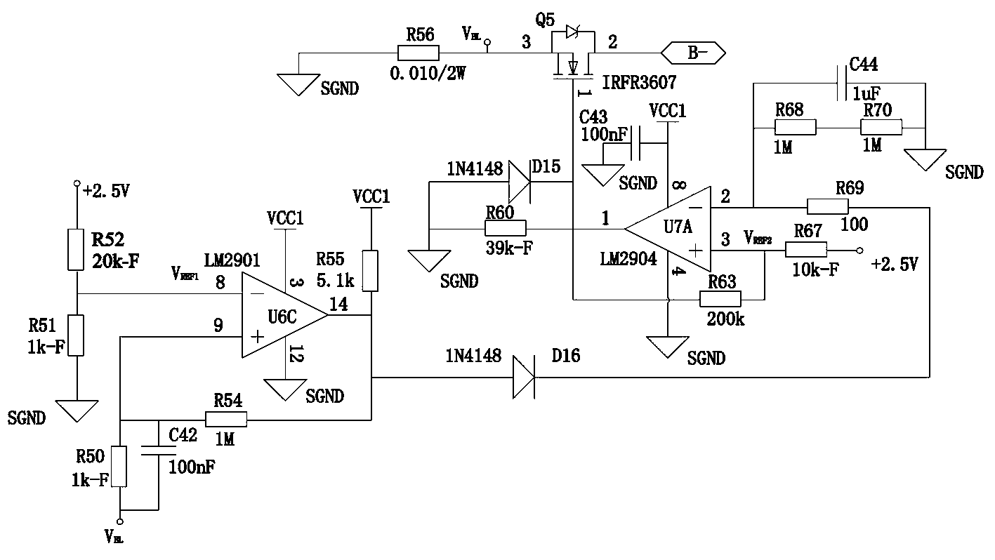
[0013] An embodiment of a float charger overcurrent protection circuit, such as figure 1 As shown, it includes an acquisition comparison circuit, a comparison control circuit, a reference voltage circuit and a MOS transistor Q5, the drain of the MOS transistor Q5 is connected to the negative pole B- of the storage battery, and the source of the MOS transistor Q5 is connected to one end of the resistor R56, The other end of the resistor R56 is grounded; the charger, the storage battery and the ground form a charging loop.

[0014] The acquisition and comparison circuit includes a comparator U6C, a resistor R54, and a resistor R55. The negative input terminal of the comparator U6C is used as a comparison reference voltage input terminal, and the output terminal of the reference voltage circuit is connected to the negative input terminal of ...


PUM


Abstract

The invention provides a floating charger over-current protection circuit which comprises a sampling comparison circuit, a comparison control circuit and a MOS tube Q5. The drain electrode of the MOS tube Q5 is connected with a cathode of a storage battery. A source electrode of the MOS tube Q5 is connected with one end of a resistor R56. The other end of the resistor R56 is grounded. The sampling comparison circuit comprises a comparator U6C, a resistor R54 and a resistor R55. The comparison control circuit comprises a resistor R60, a resistor R63, a resistor R67, a capacitor C43, a diode D15 and a comparator U7A. The floating charger over-current protection circuit is connected to the cathode of the storage battery, according to the detected voltage of the resistor R56, whether the storage battery is communicated or not is judged, the damage of the storage battery by overlarge current is prevented, the effect of over-current protection is achieved, and the floating charger over-current protection circuit has the advantages of simple circuit structure, easy implementation and good protection effect.

Description

technical field [0001] The invention relates to an overcurrent protection circuit, in particular to an overcurrent protection circuit for a float charger. Background technique [0002] At present, the battery is mostly charged by directly connecting the battery to the output terminal of the float charger. Due to the complexity of the charging site environment, when using the float charger to charge, it is easy to appear short circuit, reverse connection, excessive load, etc. The output current of the float charger output is too large, which can easily cause float charging. The components of the charger are overheated, which will damage the float charger and cause the float charger to fail to work normally. [0003] In order to solve the above existing problems, people have been seeking an ideal technical solution. Contents of the invention [0004] The object of the present invention is to address the deficiencies of the prior art, thereby providing a float charger overc...

Claims


Application Information

Patent Timeline
Patent Type & Authority Applications(China)
IPC IPC(8): H02H7/18H02J7/00
Inventor 安绍华徐红宗杨新征崔文峰王磊
Owner CHONGQING TELECOMMUNICATION INSTITUTE
Why Eureka
Try Eureka