
Compressor motor and electric compressor using same

一种电动压缩机、电动机的技术,应用在机器/发动机、机电装置、电动组件等方向,能够解决电动机电线束长度变长等问题,达到缩短导线长度的效果

Active Publication Date: 2013-09-25
MITSUBISHI HEAVY IND LTD
View PDF7 Cites 5 Cited by
  • Summary
  • Abstract
  • Description
  • Claims
  • Application Information

AI Technical Summary

Problems solved by technology

Therefore, a space for arranging the block and the motor wire harness must be formed over the entire length of the motor stator on the outer periphery of the case housing the motor. It is not always possible to make the case smaller and lighter, and the length of the motor wire harness may vary. long wait question

Method used


Image

  • Compressor motor and electric compressor using same
  • Compressor motor and electric compressor using same
  • Compressor motor and electric compressor using same

Examples


no. 1 approach

[0071] Below, use figure 1 The first embodiment of the present invention will be described with reference to FIG. 8 .

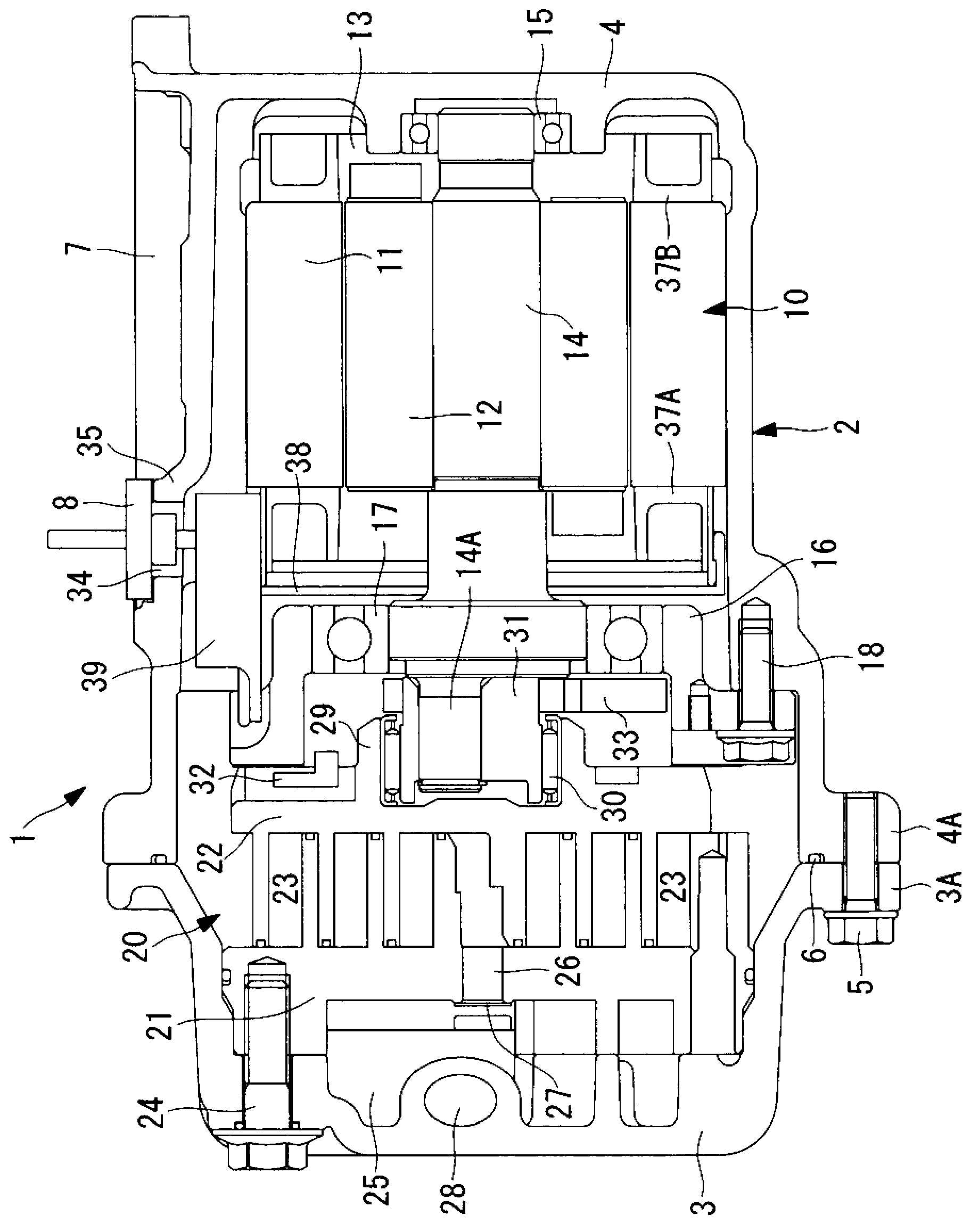
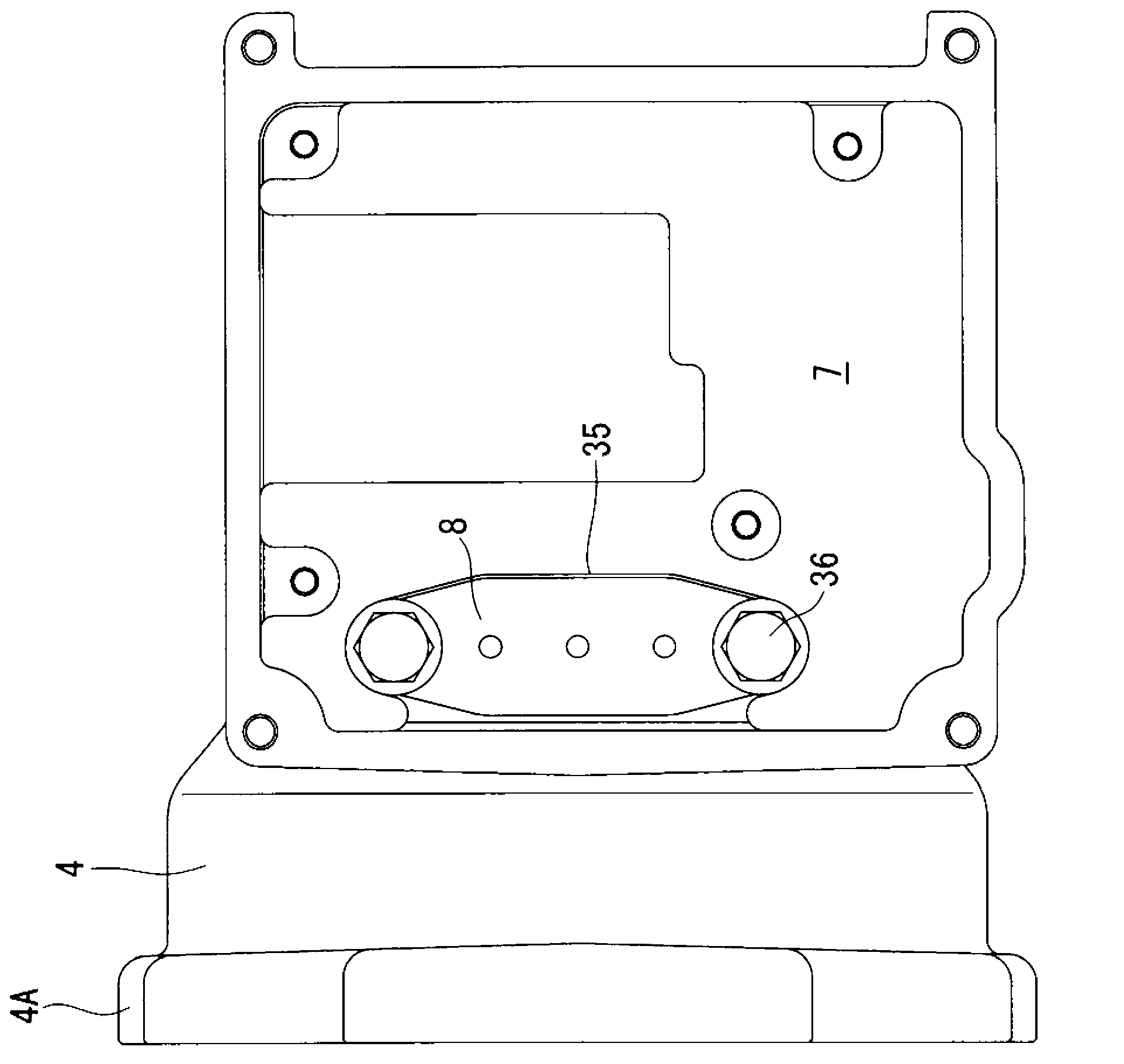
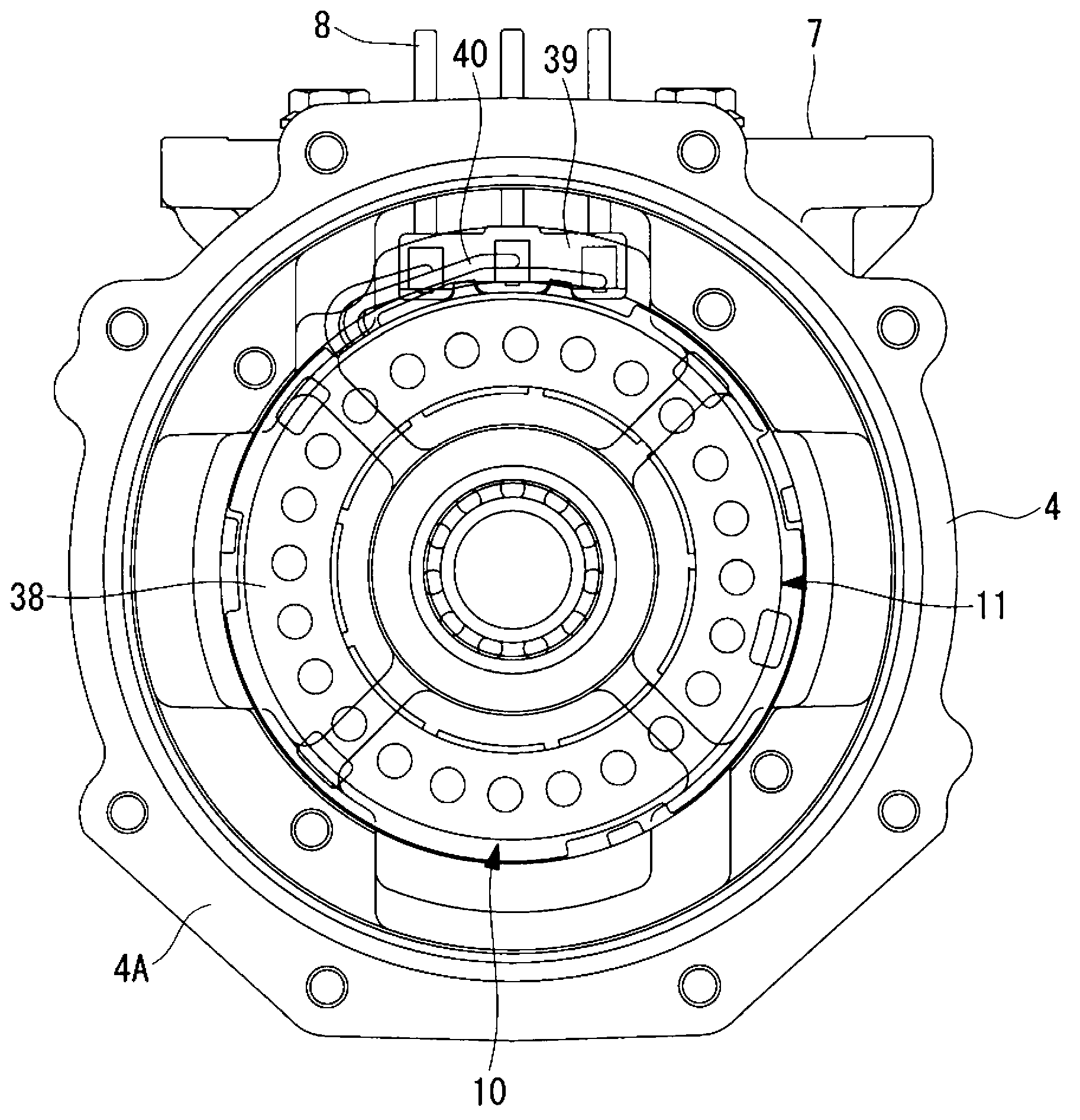
[0072] figure 1 A longitudinal sectional view showing an electric compressor according to an embodiment of the present invention without an inverter unit, figure 2 A plan view showing the motor side of the compressor, image 3 It shows the front view of the compressor motor side viewed from the compression mechanism side, Figure 4 A longitudinal sectional view showing the compressor motor side.

[0073] In this embodiment, a scroll type electric compressor 1 is illustrated as the electric compressor 1 . The electric compressor 1 has a cylindrical casing 2 constituting an outer casing. The casing 2 includes: a compressor casing 3 which is a cylindrical aluminum die-casting part with a bottom; solid and made into an integrated structure.

[0074] An inverter housing portion 7 is integrally provided on the outer periphery of the motor case 4 . In this ...

no. 2 approach

[0111] Next, a second embodiment of the present invention will be described.

[0112] This embodiment differs from the first embodiment described above in that a block 39 is provided on the bobbin 37A at the coil end of the stator 11 . Others are the same as those of the first embodiment, and description thereof will be omitted.

[0113] That is, in the present embodiment, the outer peripheral portion of the bobbin 37A on the side of the compression mechanism 20 among the pair of bobbins 37A, 37B provided at the coil ends of the stator 11 of the motor 10 uses the same arrangement as that of the first embodiment. The block 39 is constructed or provided by being sandwiched between the bobbin 37A and the stator coil end case 38 .

[0114] The bobbin 37A is made of an insulating resin material as described above, and claws etc. are integrally formed thereon, so that the block 39 can be locked, and the block 39 can be arranged in the circumferential direction and / or the axial dire...


PUM


Abstract

Provided is a compressor motor with which the motor lead wires can be shortened and the motor housing can be made more compact, and with which the size and weight of an electric compressor can be reduced; also provided is an electric compressor using this motor. A cluster block (39), which is connected to the stator coil end of a motor (10) via motor lead wires, is arranged at the outer circumferential region of the stator coil end cover (38) and a bobbin (37A) of the motor (10), with the terminal connection openings of the cluster block facing the outer circumferential side. An aperture (34) and installation bearing surface (35) which are used for inserting and installing a hermetic terminal (8) are provided at the outer circumferential region of a motor housing (4), which opposes the cluster block (39) provided on the motor (10) side. By inserting and installing the hermetic terminal (8) into the aperture (34) and onto the installation bearing surface (35) from the outer circumferential side of the motor housing (4), the terminal can be connected directly to the terminal connection openings of the cluster block (39).

Description

technical field [0001] The present invention relates to a compressor motor for applying electric power from the outside to a motor in a casing by sealing terminals, and an electric compressor using the motor. Background technique [0002] In the electric compressor, a compressor motor for driving a compression mechanism is built in a casing having a hermetically sealed structure together with the compression mechanism. Electric power is supplied to the compressor motor from the outside through the inverter through the sealed terminal provided to penetrate the case. That is, by providing a sealed terminal that penetrates the housing, the quick-connect terminal of the wire drawn from the motor coil end is connected to the sealed terminal, thereby electrically connecting the external power supply and the motor for the compressor built in the housing that is made into a sealed structure. Wiring, power supply. [0003] In this case, in a very narrow space, the quick-connect ter...

Claims


Application Information

Patent Timeline
Patent Type & Authority Applications(China)
IPC IPC(8): F04B39/00F04C29/00
CPCF04B39/121F04C18/0207F04C29/0085F04C2240/30F04C2240/40F04C2240/803F01C21/007F01C21/10F04C23/008F04D25/0606H02K5/225
Inventor 渡边贵之黑古雅司中村重贵
Owner MITSUBISHI HEAVY IND LTD
Learn More