Coordinate input device

A coordinate input device and electrode technology, applied in the input/output process of data processing, instruments, electrical digital data processing, etc., can solve the problems of increased power consumption, slow response speed, large basic capacitance, etc., and achieve power consumption Low, fast-response effects

Inactive Publication Date: 2013-09-25
ALPS ALPINE CO LTD
View PDF5 Cites 2 Cited by
  • Summary
  • Abstract
  • Description
  • Claims
  • Application Information

AI Technical Summary

Problems solved by technology

[0011] However, in the structure of Patent Document 1, since the first electrode surface 921S and the second electrode surface 922S are formed over the entire surface of the electrode, the space between the first electrode surface 921S and the ground, and between the second electrode surface 922S and the ground The base capacitance between the ground wires becomes larger
Therefore, there is such a problem that when a predetermined voltage is applied between the first electrode 921 and the second electrode 922, it takes time to apply to the base capacitance, and the voltage of the adjacent first electrode surface 921S and second electrode surface 922S is detected. The response speed required for electrostatic capacitance changes becomes slower
In addition, if the capacitance at the time of detection is large, there is a problem that the power consumption increases corresponding to this part.

Method used


Image

  • Coordinate input device
  • Coordinate input device
  • Coordinate input device

Examples


no. 1 Embodiment approach

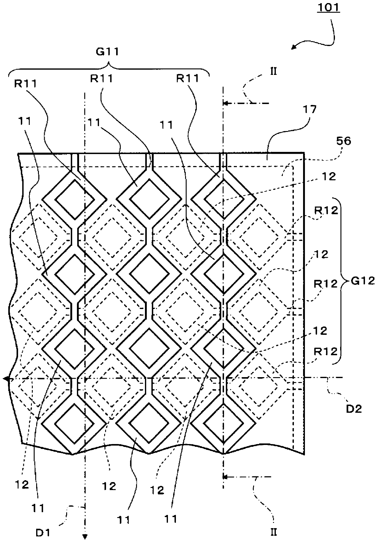
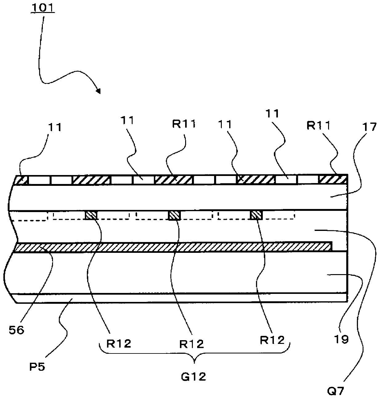
[0060] figure 1 It is a diagram illustrating the coordinate input device according to the first embodiment of the present invention, and is an enlarged structural diagram of a part of the plan view viewed from the first electrode group G11 side. figure 2 It is a figure explaining the coordinate input device of 1st Embodiment of this invention, and is figure 1 The section on line II-II is shown.

[0061] like figure 1 and figure 2 As shown, the coordinate input device 101 according to the first embodiment of the present invention is mainly composed of the first electrode group G11 provided on one side of the substrate 19, the second electrode group G12 intersecting the first electrode group G11, and The insulating layer 17 for insulating the first electrode group G11 and the second electrode group G12 is formed. In addition, its structure also has: a ground electrode part 56; an intermediate layer Q7 disposed between the first electrode group G11 and the second electro...

no. 2 Embodiment approach

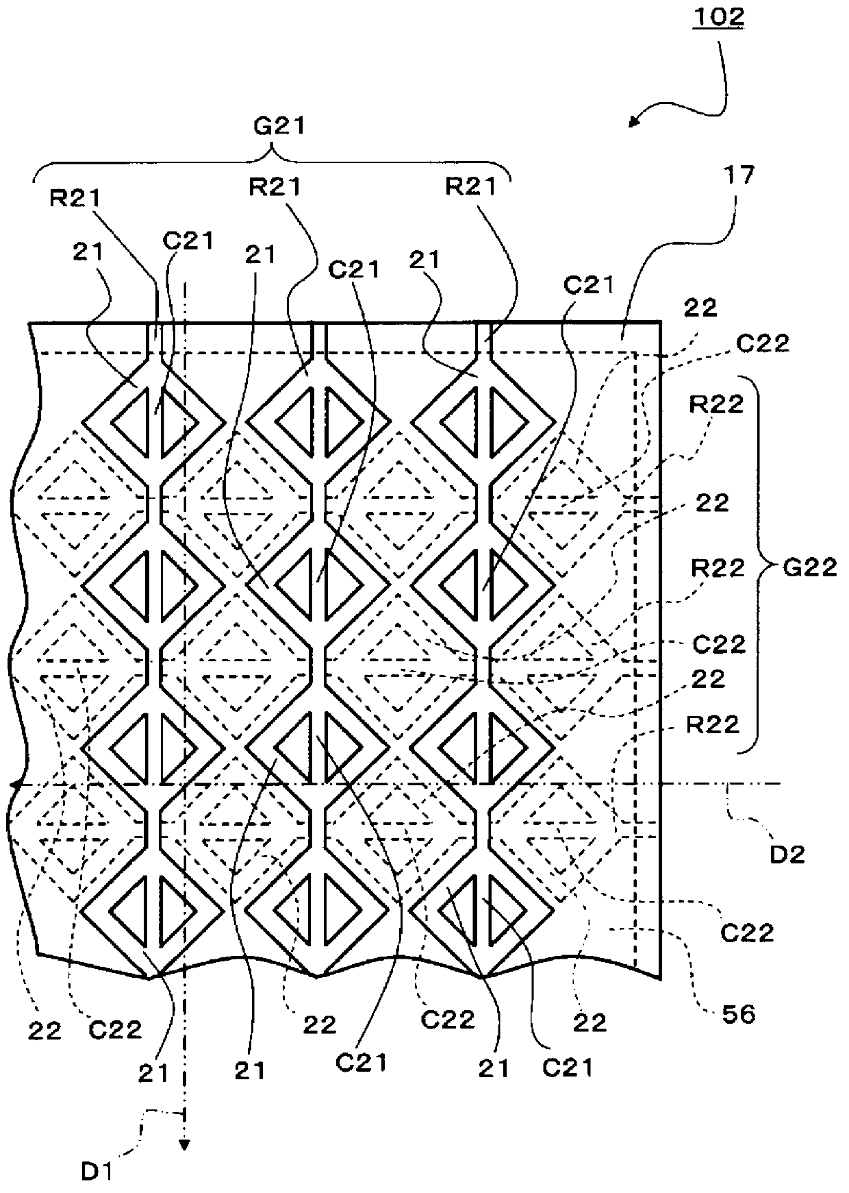
[0083] image 3 It is a diagram illustrating the coordinate input device 102 according to the second embodiment of the present invention, and is an enlarged structural diagram of a part of the plan view viewed from the first electrode group G21 side. In the coordinate input device 102 according to the second embodiment of the present invention, compared with the coordinate input device 101 according to the first embodiment of the present invention, the shape of the electrode surface of the first electrode 21 of the first electrode group G21 and the shape of the second electrode of the second electrode group G22 The shape of the electrode surface of 22 is different. In addition, the same code|symbol is attached|subjected to the same member as 1st Embodiment, and description is abbreviate|omitted.

[0084] The coordinate input device 102 according to the second embodiment of the present invention, like the coordinate input device 101 according to the first embodiment, is mainly...

no. 3 Embodiment approach

[0092] Figure 4 It is a diagram illustrating the coordinate input device 103 according to the third embodiment of the present invention, and is an enlarged structural diagram of a part of the plan view viewed from the first electrode group G31 side. Figure 5 is a diagram illustrating the coordinate input device 103 according to the third embodiment of the present invention, and is Figure 4Sectional view on line V-V shown. The coordinate input device 103 according to the third embodiment of the present invention differs from the coordinate input device 102 according to the second embodiment of the present invention in that a third electrode 33 and a fourth electrode 34 are newly provided. In addition, the other structural elements and the arrangement relationship of each structural element are the same as those of the coordinate input device 102 of the second embodiment. In addition, the same code|symbol is attached|subjected to the same member as 1st Embodiment and 2nd Em...


PUM


Abstract

The objective of the present invention is to provide a coordinate input device having a high response speed at the time of detection, and having reduced power consumption. This capacitance-type coordinate input device is provided with: a first electrode group comprising a plurality of first electrode arrays arranged at a predetermined interval; and a second electrode group comprising a plurality of second electrode arrays arranged at a predetermined interval, wherein the first electrode group and the second electrode group are isolated, and laid in order to intersect each other, the first electrode arrays comprise a plurality of first electrodes connected in the first direction, the second electrode arrays comprise a plurality of second electrodes connected in the second direction, the first electrodes are arranged to be offset from the second electrodes in the plan view, and the shape of the first electrode and the shape of the second electrode are annular shapes.

Description

technical field [0001] The present invention relates to a coordinate input device having a contact surface touched by an operator's fingertip or the like, and detecting the contact position of the fingertip or the like on the contact surface. Background technique [0002] In recent years, notebook-type personal computers (notebook PCs), mobile phones, and portable terminals have been widely spread. In the field of ordinary computers, the mouse has been widely used as a device for moving the cursor on the display screen, but in the fields where mobility is important, a contact surface that is touched by the operator's fingertips is often used to detect fingertips. A coordinate input device for the contact position of the contact surface. Coordinate input devices are often used in input touch panels of personal computers and the like, and are also applied to touch panels of mobile devices and various terminals by using transparent substrates and transparent electrodes. [00...

Claims


Application Information

Patent Timeline
Patent Type & Authority Applications(China)
IPC IPC(8): G06F3/041G06F3/044
CPCG06F2203/04111G06F3/0445G06F3/0446G06F3/0448
Inventor 尾屋隼一郎
Owner ALPS ALPINE CO LTD
Why Eureka
Try Eureka