Rotary compressor
A rotary compressor and compression pump technology, applied in the field of compressors, can solve the problems of reduced compressor performance, increased viscous resistance of the exhaust valve plate, and affecting the heat exchange effect of the air conditioning system, so as to improve performance and increase the exchange rate. The effect of thermal effects
- Summary
- Abstract
- Description
- Claims
- Application Information
AI Technical Summary
Problems solved by technology
Method used
Image
Examples
no. 1 example
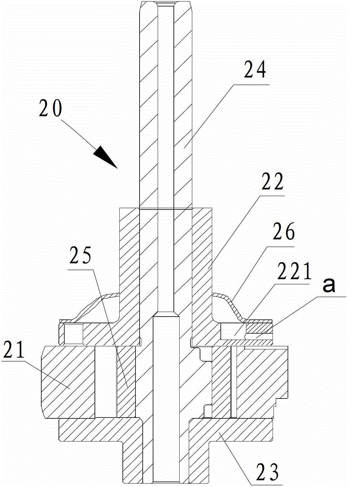
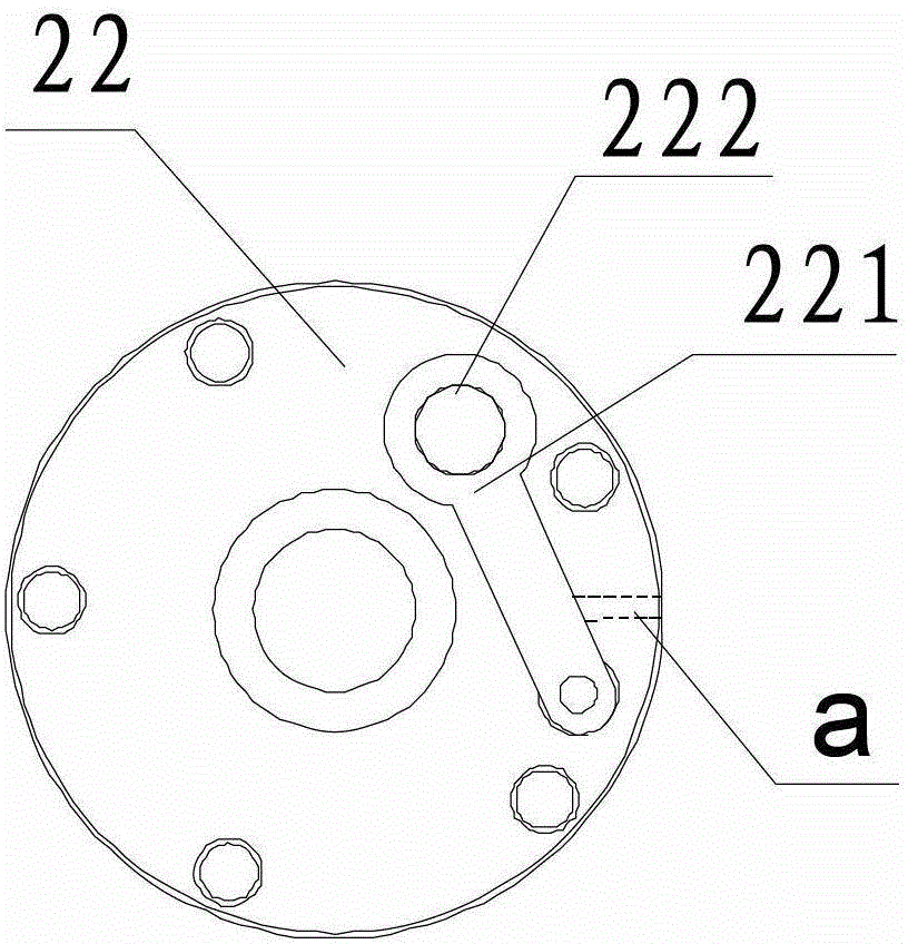
[0031] Such as figure 2 and image 3 Shown is the first embodiment of the compression pump body of the rotary compressor of the present invention. In this embodiment, the rotary compressor includes a casing (not shown in the figure) and a compression pump body 20 disposed in the casing. The bottom of the housing is provided with an oil pool for storing lubricating oil. The compression pump body 20 includes a cylinder 21, a main bearing 22, an auxiliary bearing 23, a crankshaft 24 and a rolling piston 25. The main bearing 22 and the auxiliary bearing 23 are correspondingly installed on the upper and lower end surfaces of the cylinder 21, and the rolling piston 25 is arranged on the cylinder 21. Inside, and rotate under the drive of crankshaft 24. In order to reduce the airflow noise generated by the exhaust, a muffler 26 for noise reduction is installed on the upper end of the main bearing 22 .
[0032] The main bearing 22 is provided with a valve seat recess 221, an exhau...
no. 2 example
[0036] Such as Figure 4 to Figure 6Shown is the second embodiment of the compression pump body of the rotary compressor of the present invention. In this embodiment, the rotary compressor includes a casing (not shown in the figure) and a compression pump body 30 disposed in the casing. The bottom of the housing is provided with an oil pool for storing lubricating oil. The compression pump body 30 includes a cylinder 31, a main bearing 32, an auxiliary bearing 33, a crankshaft 34 and a rolling piston 35. The main bearing 32 and the auxiliary bearing 33 are installed on the upper and lower end faces of the cylinder 31, and the rolling piston 35 is arranged on the cylinder 31. Inside, and rotate under the drive of crankshaft 34. In order to reduce the airflow noise generated by the exhaust, a muffler 36 for noise reduction is installed on the upper end of the main bearing 32 .
[0037] The main bearing 32 is provided with a valve seat recess 321 , an exhaust hole 322 and a fi...
no. 3 example
[0040] Such as Figure 7 Shown is the third embodiment of the compression pump body of the rotary compressor of the present invention. In this embodiment, the rotary compressor includes a casing (not shown in the figure) and a compression pump body 40 disposed in the casing. The bottom of the housing is provided with an oil pool for storing lubricating oil. The compression pump body 40 includes a cylinder 41, a main bearing 42, an auxiliary bearing 43, a crankshaft 44 and a rolling piston 45. The main bearing 42 and the auxiliary bearing 43 are correspondingly installed on the upper and lower end surfaces of the cylinder 41, and the rolling piston 45 is arranged on the cylinder 41. Inside, and rotate under the drive of crankshaft 44. In order to reduce the airflow noise generated by the exhaust, a muffler 46 for noise reduction is installed on the upper end of the main bearing 42 .
[0041] The main bearing 42 is provided with a valve seat recess 421 , an exhaust hole (not ...
PUM
 Abstract
Description
Claims
Application Information
 - R&D
- Intellectual Property
- Life Sciences
- Materials
- Tech Scout
- Unparalleled Data Quality
- Higher Quality Content
- 60% Fewer Hallucinations
Browse by: Latest US Patents, China's latest patents, Technical Efficacy Thesaurus, Application Domain, Technology Topic, Popular Technical Reports.
© 2025 PatSnap. All rights reserved.Legal|Privacy policy|Modern Slavery Act Transparency Statement|Sitemap|About US| Contact US: help@patsnap.com


