
Low-cost analog linear optocoupler

A linear optocoupler, low-cost technology, used in signal transmission systems, instruments, electrical signal transmission systems, etc., can solve the problems of increasing system cost, complex and expensive systems, and expensive linear optocouplers. low cost effect

Inactive Publication Date: 2013-10-02
XIDIAN UNIV
View PDF2 Cites 0 Cited by
  • Summary
  • Abstract
  • Description
  • Claims
  • Application Information

AI Technical Summary

Problems solved by technology

[0003] The currently known solution is to use a linear optocoupler, but the linear optocoupler is expensive, which will increase the cost of the system, and the output of the linear optocoupler is a differential signal
An instrumentation amplifier is required to convert the differential signal to a common-mode single-ended signal, making the system more complex and expensive

Method used


Image

  • Low-cost analog linear optocoupler
  • Low-cost analog linear optocoupler

Examples


Embodiment Construction

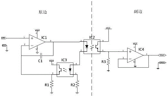
[0014] Such as figure 1 Shown is a circuit diagram of a low-cost analog linear optocoupler of the present invention. A low-cost analog linear optocoupler includes: a first operational amplifier IC1, a second operational amplifier IC4, a first optocoupler IC2, a second optocoupler IC3, The first resistor R1, the second resistor R2, the third resistor R3, the capacitor C1, the primary power supply VDD, the primary ground GND, the secondary power supply VCC, the secondary ground GND2, the positive input terminal VIN and the positive output terminal Vout, wherein the first An operational amplifier IC1 pin 1 is connected to the input signal, and the first operational amplifier IC1 pin 4 and pin 5 are respectively connected to the primary side power supply VDD and the primary side GND capacitor C1 is connected to the first operational amplifier IC1 pin 3 and pin Between 2, pin 3 of the first operational amplifier IC1 is connected to pin 1 of the first optocoupler IC2, pin 2 of the ...


PUM


Abstract

The invention discloses a low-cost analog linear optocoupler, which includes a first operational amplifier (IC1), a second operational amplifier (IC4), a first optocoupler (IC2), a second optocoupler (IC3), a first resistor (R1), a second resistor (R2), a third resistor (R3), a capacitor (C1), a primary side power source (VDD), a primary side area (GND), a secondary side power source (VCC), a secondary side area (GND2), a positive input end (VIN) and a positive output end (Vout), wherein light emitting diodes of the two optocouplers are connected in series, so that electric currents flowing through the two light emitting diodes are consistent, isolation feedback is realized, a circuit is enabled to work steadily, complete electric isolation between the primary side and the secondary side is realized, systems on two sides can be isolated on the premise that transmission of analog signals is realized, and influences are avoided. Meanwhile, the circuit has ideal output impedance, so that the treatment of a rear connection system is facilitated. The low-cost analog linear optocoupler is simple in structure and connection, is low in cost, can replace expensive linear optocouplers to realize isolation transmission of the analog signals.

Description

technical field [0001] The invention belongs to the field of analog signal isolation transmission and relates to an analog linear optocoupler circuit. Background technique [0002] In many industrial site signal acquisition systems and control systems, it is necessary to collect and know the analog signals of the industrial site, and the collected signals work in harsh environments, often accompanied by extremely high common-mode interference and spike signals. If these common-mode interferences are introduced In the post-processing system, the system will often fail to work or even be damaged, which will cause production accidents on the industrial site. Therefore, the isolation and transmission of analog signals plays an extremely important role in many circuit systems. [0003] The currently known solution is to use a linear optocoupler, but the linear optocoupler is expensive, which will increase the cost of the system, and the output of the linear optocoupler is a diff...

Claims


Application Information

Patent Timeline
IPC IPC(8): G01D5/56G08C19/36
Inventor 李平刘淑芳张庞源李蕊杨福荣史小卫
Owner XIDIAN UNIV
Learn More