
High-precision distributed optical fiber temperature sensing system

A distributed optical fiber, sensing system technology, applied in thermometers, thermometers with physical/chemical changes, measurement devices, etc. Accuracy and other issues

Inactive Publication Date: 2013-10-02
WEIHAI BEIYANG PHOTOELECTRIC INFORMATION TECH
View PDF8 Cites 2 Cited by
  • Summary
  • Abstract
  • Description
  • Claims
  • Application Information

AI Technical Summary

Problems solved by technology

However, due to the large wavelength difference between the Stokes light and the anti-Stokes light, the refractive index in the optical fiber is different, and the propagation speed of the two in the optical fiber is different, the data collected by the data acquisition unit is the data at the same time, while data not in the same location
Therefore, the time-domain reflection curves of Stokes light and anti-Stokes light will appear "step difference", which will reduce the spatial resolution, positioning accuracy and temperature measurement accuracy of the system, and even cause temperature calculation errors
[0004] The patent "A Distributed Optical Fiber Raman Temperature Sensor with Dispersion and Loss Spectrum Self-calibration" (Application No.: 201020157461.7) proposes to use dual light sources to realize the self-calibration of dispersion and loss spectra, but it needs to add a light source, accounting for 1 of the main cost / 3 or so

Method used


Image

  • High-precision distributed optical fiber temperature sensing system
  • High-precision distributed optical fiber temperature sensing system
  • High-precision distributed optical fiber temperature sensing system

Examples


Embodiment Construction

[0040] The present invention will be further described below in conjunction with the accompanying drawings and embodiments, but not as a basis for limiting the present invention.

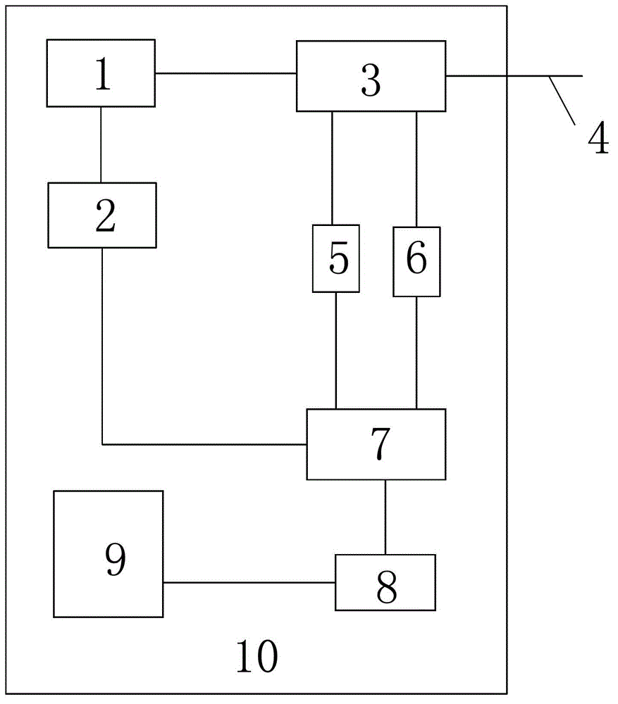
[0041] Example. A high-precision distributed optical fiber temperature sensing system, such as figure 1 As shown, including the system housing 10, the system housing 10 is provided with a laser 1, the input end of the laser 1 is connected with the output end of the laser driving module 2, the output end of the laser 1 is connected with the input end of the optical splitting filter module 3, and the optical splitting filter module One output end of 3 is connected to the optical fiber 4, and the other two output ends are respectively connected to the input ends of the first photoelectric conversion module 5 and the second photoelectric conversion module 6. The output of the first photoelectric conversion module 5 and the second photoelectric conversion module 6 The terminals are all connected with th...


PUM


Abstract

The invention discloses a high-precision distributed optical fiber temperature sensing system. According to the system, different sampling rates are set for a data acquisition unit according to the characteristic of different wavelengths of stokes and anti-stokes to ensure that each pair of acquired stokes and anti-stokes data corresponds to a position on an optical fiber; the influence of the different wavelengths of the stokes and the anti-stokes on spatial resolution, positioning precision and temperature precision is eliminated fundamentally; the three key indexes of the system are improved; and the application scope of the distributed optical fiber temperature sensing system is expanded.

Description

technical field [0001] The invention relates to a high-precision distributed optical fiber temperature sensing system, in particular to a high-precision distributed optical fiber temperature sensing system based on the Raman dispersion principle. Background technique [0002] The distributed optical fiber temperature sensing system is composed of two parts: the host computer and the optical fiber. It can detect the temperature information of all positions along the optical fiber laying line, and realize the monitoring of long-distance oil and gas pipelines and the full-range temperature monitoring of ultra-long-distance power cables. With the characteristics of safety and long life, it can be widely used in power systems, cable tunnel fire detection applications, oil pipeline or storage tank leakage monitoring, etc. To achieve the purpose of prevention in advance, to ensure the safety of national property and people's lives. [0003] The working principle of the existing di...

Claims


Application Information

Patent Timeline
IPC IPC(8): G01K11/32G01K11/324
Inventor 张文平冯军胡文贵祝海钟温天兵
Owner WEIHAI BEIYANG PHOTOELECTRIC INFORMATION TECH
Learn More