Fault correlation domain identification system based on fault component reactive power and method thereof

A fault component and identification system technology, applied in the measurement of electricity, measurement devices, measurement of electrical variables, etc., can solve problems such as insufficient sensitivity, secondary system paralysis, and lack of research, to improve safety, solve protection problems, and protect performance. Sensitive and reliable effects

Active Publication Date: 2013-10-02
NORTH CHINA ELECTRIC POWER UNIV (BAODING)
View PDF3 Cites 13 Cited by
  • Summary
  • Abstract
  • Description
  • Claims
  • Application Information

AI Technical Summary

Problems solved by technology

[0005] 2) The law of energy conservation is applicable to closed areas of any range, so using power information to identify fault-related domains has unique advantages. At present, there are relatively few studies in this area, and active exploration should be carried out while problem 1) is solved
[0006] At the same time, the loss of DC in the substation will lead to the paralysis of the secondary system in the substation, a...

Method used


Image

  • Fault correlation domain identification system based on fault component reactive power and method thereof
  • Fault correlation domain identification system based on fault component reactive power and method thereof
  • Fault correlation domain identification system based on fault component reactive power and method thereof

Examples


Embodiment 1

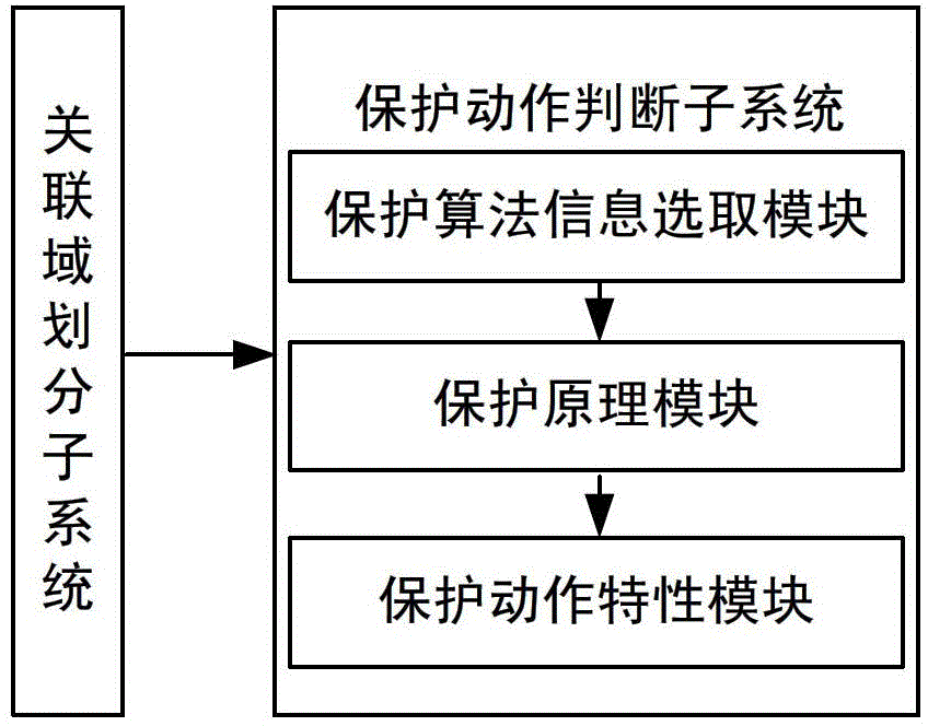
[0061] (1) Associated Domain Division Subsystem

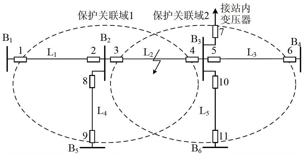
[0062] Based on the IEEE39 node system model for simulation analysis, the electrical wiring diagram is as follows Figure 5 shown. Substation B 19 and B 20 Construct protection association domain 1 and protection association domain 2 as the center, protection association domain 1 includes bus B 19 and line L 16-19 , L 19-20 , L 19-33 , the protection association domain 2 contains bus B 20 and line L 19-20 , L 20-34 . Taking the two as examples, the simulation analysis of the fault correlation domain identification method based on fault component reactive power is carried out.

[0063] The emulation type is set as follows: 1) Line L 19-20 Three-phase fault, two-phase ground fault, two-phase fault, single-phase fault and single-phase ground fault through 100Ω resistance occur at the midpoint; 2) Bus B 19 Three-phase fault, two-phase ground fault, two-phase fault, single-phase fault and single-phase ground fault throug...

Embodiment 2

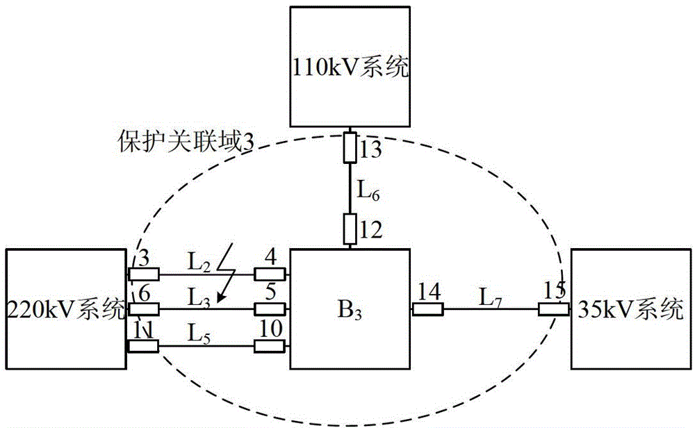
[0084] by Figure 9 The network shown is taken as an example to simulate and analyze the action performance of the fault correlation domain identification method in the case of substation DC disappearance.

[0085] The parameters of the components in the grid are as follows, the M-side system: Z MS1 =4.5∠80°Ω, Z MS0 =5.0∠80°Ω; N side system: Z MS1 =15.0∠80°Ω, Z MS0 =18.0∠80°Ω; P side system: Z MS1 =20.0∠80°Ω, Z MS0 =∞; transformer parameters: winding structure is YNyn0d11, S 1N / S 2N / S 3N =300 / 300 / 300MVA, U 1N / U 2N / U 3N =220 / 110 / 35kV, U k(1-2) %=11.27%, U k(2-3) %=8.21%, U k(3-1) %=15.14%, ignoring transformer resistance and excitation branch; line L 1 , L 2 , L 3 Parameter: Z L1 =0.034+0.405jΩ / km, Y C1 =3.007×10 -6 jS / km, Z L0 =0.287+1.005jΩ / km, Y C0 =1.132×10 -6 jS / km, l=50km.

[0086] Simulation type setting: 1) Line L in the area 1 , L 2 Midpoint K 1 、K 2 Three-phase fault, two-phase grounding, two-phase fault, si...


PUM


Abstract

The invention relates to a fault correlation domain identification system based on fault component reactive power and a method thereof and belongs to the electric power system fault identification technology field. The fault correlation domain identification system comprises a correlation domain division subsystem and a protection motion determination subsystem, wherein the correlation domain division subsystem takes each start protection station as a center and takes a same voltage grade outgoing line pair end station as a boundary division protection correlation domain, the protection motion determination subsystem realizes establishment of a protection algorithm model, a protection algorithm information selection module extracts fault component reactive power in a fault association domain, a protection principle module realizes construction of protection action quantity and braking quantity based on the fault component reactive power, a protection motion characteristic module determines and identifies the fault association domain according to protection action. The fault correlation domain identification system can respectively acquire accurate determination results during occurrence of each types of faults in and out of the fault correlation domain, has sensitive and reliable protection performance, not only realizes an electrical network remote backup protection function under a common condition, but also successively solves a problem of protection difficulty under a condition of direct current disappearance of a transformer station and further improves electrical network security.

Description

technical field [0001] The invention relates to a fault correlation domain identification system based on fault component reactive power and a method thereof, and belongs to the technical field of fault identification of substation power systems. technical background [0002] The relay protection configuration in high-voltage transmission lines basically uses current differential protection and distance protection as dual protection, of which distance three-stage protection is used as backup protection. However, distance backup protection only uses local information to respond to faults, and objectively, it can only adopt a step-by-step coordination method to remove faults, resulting in various defects. On-line self-adaptive setting and power flow transfer identification take advantage of wide-area multi-information, but do not innovate the way of protection step-by-step coordination, so part of the performance is mainly improved. The emergence of the fault identification a...

Claims


Application Information

Patent Timeline
IPC IPC(8): G01R31/00G06F19/00
Inventor 马静姜宪国王增平马伟朱祥胜
Owner NORTH CHINA ELECTRIC POWER UNIV (BAODING)
Why Eureka
Try Eureka