Fault Correlation Domain Identification System and Method Based on Fault Component Reactive Power
A fault component and identification system technology, applied in the direction of measuring electricity, measuring devices, measuring electrical variables, etc., can solve the problems of paralysis of the secondary system, insufficient sensitivity, and lack of research, to improve safety, solve protection problems, and protect performance. Sensitive and reliable effects
- Summary
- Abstract
- Description
- Claims
- Application Information
AI Technical Summary
Problems solved by technology
Method used
Image
Examples
Embodiment 1
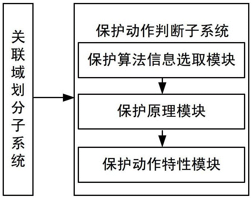
[0061] (1) Associated Domain Division Subsystem
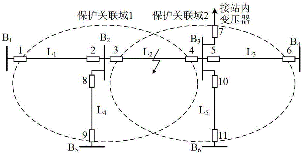
[0062] Based on the IEEE39 node system model for simulation analysis, the electrical wiring diagram is as follows Figure 5 shown. Substation B 19 and B 20 Construct protection association domain 1 and protection association domain 2 as the center, protection association domain 1 includes bus B 19 and line L 16-19 , L 19-20 , L 19-33 , the protection association domain 2 contains bus B 20 and line L 19-20 , L 20-34 . Taking the two as examples, the simulation analysis of the fault correlation domain identification method based on fault component reactive power is carried out.
[0063] The emulation type is set as follows: 1) Line L 19-20 Three-phase fault, two-phase ground fault, two-phase fault, single-phase fault and single-phase ground fault through 100Ω resistance occur at the midpoint; 2) Bus B 19 Three-phase fault, two-phase ground fault, two-phase fault, single-phase fault and single-phase ground fault throug...
Embodiment 2
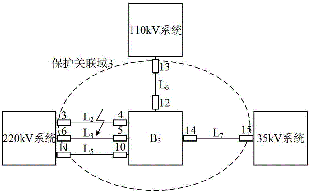
[0084] by Figure 9 The network shown is taken as an example to simulate and analyze the action performance of the fault correlation domain identification method in the case of substation DC disappearance.
[0085] The parameters of the components in the grid are as follows, the M-side system: Z MS1 =4.5∠80°Ω, Z MS0 =5.0∠80°Ω; N side system: Z MS1 =15.0∠80°Ω, Z MS0 =18.0∠80°Ω; P side system: Z MS1 =20.0∠80°Ω, Z MS0 =∞; transformer parameters: winding structure is YNyn0d11, S 1N / S 2N / S 3N =300 / 300 / 300MVA, U 1N / U 2N / U 3N =220 / 110 / 35kV, U k(1-2) %=11.27%, U k(2-3) %=8.21%, U k(3-1) %=15.14%, ignoring transformer resistance and excitation branch; line L 1 , L 2 , L 3 Parameter: Z L1 =0.034+0.405jΩ / km, Y C1 =3.007×10 -6 jS / km, Z L0 =0.287+1.005jΩ / km, Y C0 =1.132×10 -6 jS / km, l=50km.
[0086] Simulation type setting: 1) Line L in the area 1 , L 2 Midpoint K 1 、K 2 Three-phase fault, two-phase grounding, two-phase fault, single-phase grounding, si...
PUM
 Abstract
Description
Claims
Application Information
 - R&D
- Intellectual Property
- Life Sciences
- Materials
- Tech Scout
- Unparalleled Data Quality
- Higher Quality Content
- 60% Fewer Hallucinations
Browse by: Latest US Patents, China's latest patents, Technical Efficacy Thesaurus, Application Domain, Technology Topic, Popular Technical Reports.
© 2025 PatSnap. All rights reserved.Legal|Privacy policy|Modern Slavery Act Transparency Statement|Sitemap|About US| Contact US: help@patsnap.com


