
Dual-polarized broadband antenna radiation device

A broadband antenna and radiating device technology, applied in the field of dual-polarized broadband antenna radiating devices, can solve the problems of difficult matching, increase manufacturing cost, heavy weight, etc., and achieve the effects of slowing down impedance changes, saving raw materials, and reducing weight

Active Publication Date: 2013-10-02
CHANGSHU HONGBO COMM TECH CO LTD
View PDF4 Cites 11 Cited by
  • Summary
  • Abstract
  • Description
  • Claims
  • Application Information

AI Technical Summary

Problems solved by technology

However, there are disadvantages in the following three aspects: First, due to the unreasonable structure of the radiation unit arm, the current distribution on the radiation unit arm cannot achieve the desired effect, which is specifically manifested in the extension of the impedance bandwidth of the radiation unit arm The effect is poor, that is, the effect of widening the impedance bandwidth is poor; secondly, because the shape of the hollow gap between the adjacent radiating unit arms is unreasonable, it is not enough to make the impedance of the radiating unit arms change with the frequency. Matching is achieved in a wide frequency range, which suppresses the bandwidth of the radiating unit arm; third, due to the unreasonable structure of the radiating unit arm, the weight is large, which not only wastes materials, but also increases manufacturing costs

Method used


Image

  • Dual-polarized broadband antenna radiation device
  • Dual-polarized broadband antenna radiation device

Examples


Embodiment Construction

[0019] In order to enable the examiners of the patent office, especially the public, to understand the technical essence and beneficial effects of the present invention more clearly, the applicant will describe in detail the following in the form of examples, but none of the descriptions to the examples is an explanation of the solutions of the present invention. Any equivalent transformation made according to the concept of the present invention which is merely formal but not substantive shall be regarded as the scope of the technical solution of the present invention.

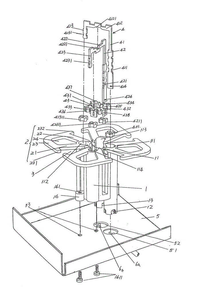
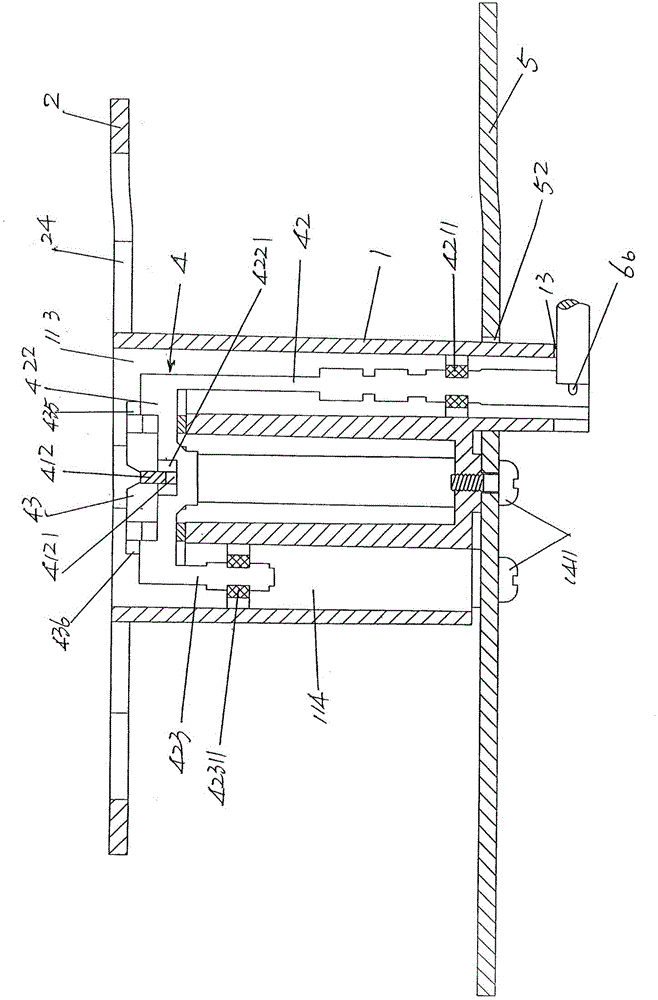
[0020] See figure 1 with figure 2 In order to facilitate the public's understanding, the applicant shows a metal reflection plate 5 for installing the present invention in the figure, and the metal reflection plate 5 is provided with first and second feeding connection socket matching holes 51, 52, and a pair of feeding connection seat fixing holes 53 are also provided. According to common knowledge, a plur...


PUM


Abstract

A dual-polarized broadband antenna radiation device belongs to the technical field of mobile communication base station antennas and comprises a feeding connection seat, a group of radiating element arms and a feeding mechanism, wherein a feeding mechanism cavity is formed in the center of the feeding connection seat; the radiating element arms are distributed around the feeding connection seat; the feeding mechanism is inserted in the feeding mechanism cavity. The dual-polarized broadband antenna radiation device is characterized in that each radiating element arm comprises a first oscillator arm, a second oscillator arm and a radiating arm, wherein one ends of the first and second oscillator arms are connected with the top of the feeding connection base; the other ends of the first and second oscillator arms extend away from the feeding connection seat; one end of the radiating arm is connected with the other end of the first oscillator arm to form a first expansion end; the other end of the radiating arm is connected with the other end of the second oscillator arm to form a second expansion end; the first oscillator arm, the second oscillator arm and the radiating arm form a space which serves as a hollow cavity; the hollow cavity is rhombus-shaped; hollow gaps are trapezoid. The dual-polarized broadband antenna radiation device has the advantages that current distribution on the radiating element arms can be changed; the impedance change of the radiating element arms is slowed down; the weight is reduced and raw materials are saved.

Description

technical field [0001] The invention belongs to the technical field of mobile communication base station antennas, and in particular relates to a dual-polarized broadband antenna radiation device. Background technique [0002] The dual-polarized broadband antenna radiating device is usually called the dual-polarized broadband antenna radiating unit, and there is no lack of technical information about this antenna in the published Chinese patent documents, such as the typical invention patent application publication number CN102157783A recommending "double Polarized broadband radiating unit and array antenna", has two groups and each group has a pair of radiating unit arms, and each radiating oscillator arm is fan-shaped; the authorized announcement number CN203013922U provides "ultra-wideband dual-polarized base station antenna radiating unit", which discloses There are two pairs of four radiating unit arms, and each radiating unit arm is generally in the shape of a hollowe...

Claims


Application Information

Patent Timeline
Patent Type & Authority Applications(China)
IPC IPC(8): H01Q21/24H01Q1/36
Inventor 庄昆徐澄宇
Owner CHANGSHU HONGBO COMM TECH CO LTD
Learn More