Transport device

A technology of transportation device and guide rail, applied in transportation and packaging, underground transportation, track, etc., can solve the problem of unavoidable high wear of gears, and achieve the effect of reducing quantity, improving traction and simple structure

Active Publication Date: 2013-10-02
SMT SCHARF
View PDF8 Cites 7 Cited by
  • Summary
  • Abstract
  • Description
  • Claims
  • Application Information

AI Technical Summary

Problems solved by technology

In addition, due to the constant meshing of the various g

Method used


Image

  • Transport device
  • Transport device
  • Transport device

Examples


Embodiment Construction

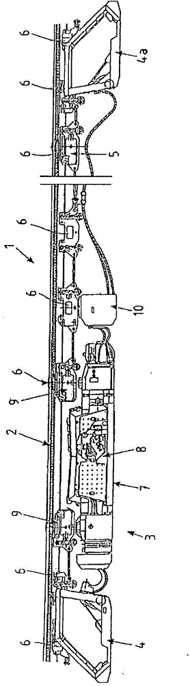
[0052] FIG. 1 shows a transport device 1 known from the prior art (DE 42 20 527 A1), which comprises an I-shaped guide rail 2 and a suspension movable on the guide rail 2 in the form of a monorail suspension rail. Transport trains for underground mining 3.

[0053] The transport train 3 has a driver's cab 4 , 4 a at both ends and a transport carriage 5 , not shown in detail, between the driver's cabs 4 , 4 a. The driver's cab 4 , 4 a and the transport carriage 5 can be moved along the guide rail 2 by means of the undercarriage 6 .

[0054] Connected to the driver's cab 4 is a tractor 7 which is provided with a diesel-hydraulic drive 8 . The tractor 7 has two drive units 9 . Following the tractor 7 is a cooling device 10 suspended on the guide rail 2 via the undercarriage 6 .

[0055] A toothed rack (not shown in detail) is provided in sections above the guide rail 2 , which meshes with a gear wheel of the drive unit 9 when the friction wheel, which is also present, is lifte...


PUM


Abstract

The transport device comprises a guide rail (2), which is composed of rail segments, and a transport train, which can be moved while suspended on the guide rail and which has at least one gear (11) that interacts with the guide rail (2) as a component of a driving unit (9) of a tractor of the transport train. The guide rail (2) has two bar-like flanges (19, 23) that extend parallel to each other and several bolts (13) that connect the flanges (19, 23) arranged one over the other to each other. The gear (11) is always operatively engaged with the bolts (13). Furthermore, the driving unit (9) is supported by means of support rollers (17) on the inside (18) of the lower flange (19).

Description

technical field [0001] The invention relates to a transport device according to the features of the preamble of claim 1 . Background technique [0002] Such a transport device is also known under the term "monorail suspension rail system" (in particular for underground mining). In many cases, the transport train is advanced by means of a drive unit with friction wheels which are pressed from the side of the guide rail formed by the guide rail segments onto the webs of the guide rail segments. Each friction wheel can only transmit a limited amount of driving force due to the strongly varying coefficient of friction (with values ​​between 0.2 and 0.5). This driving force is mostly sufficient under relatively light loads in horizontal operation. However, it is common in practice to connect a plurality of drive units to the drive system when relatively large loads are being pulled and in addition ascents as well as descents have to be overcome. This is combined with a relativ...

Claims


Application Information

Patent Timeline
IPC IPC(8): B61B3/02B61B13/02B61B13/04E01B25/22
CPCB61B3/02B61B13/02B61B13/04E01B25/22E21F13/00
Inventor G·贝劳
Owner SMT SCHARF
Why Eureka
Try Eureka