

High-speed main shaft cooling device
A technology of cooling device and high-speed spindle, which is applied in the direction of metal processing machinery parts, maintenance and safety accessories, metal processing equipment, etc., can solve the problem of unsatisfactory cooling effect, achieve good cooling effect, improve service life, and prevent damage Effect
Inactive Publication Date: 2013-10-09
玉环三丰阀门股份有限公司
View PDF6 Cites 11 Cited by
- Summary
- Abstract
- Description
- Claims
- Application Information
AI Technical Summary
Problems solved by technology
However, since the cooling device uses a cooling water circulation system to cool the spindle shell, the cooling effect is not ideal
Method used
View moreImage
Smart ImageViewing Examples

Examples
Embodiment 2
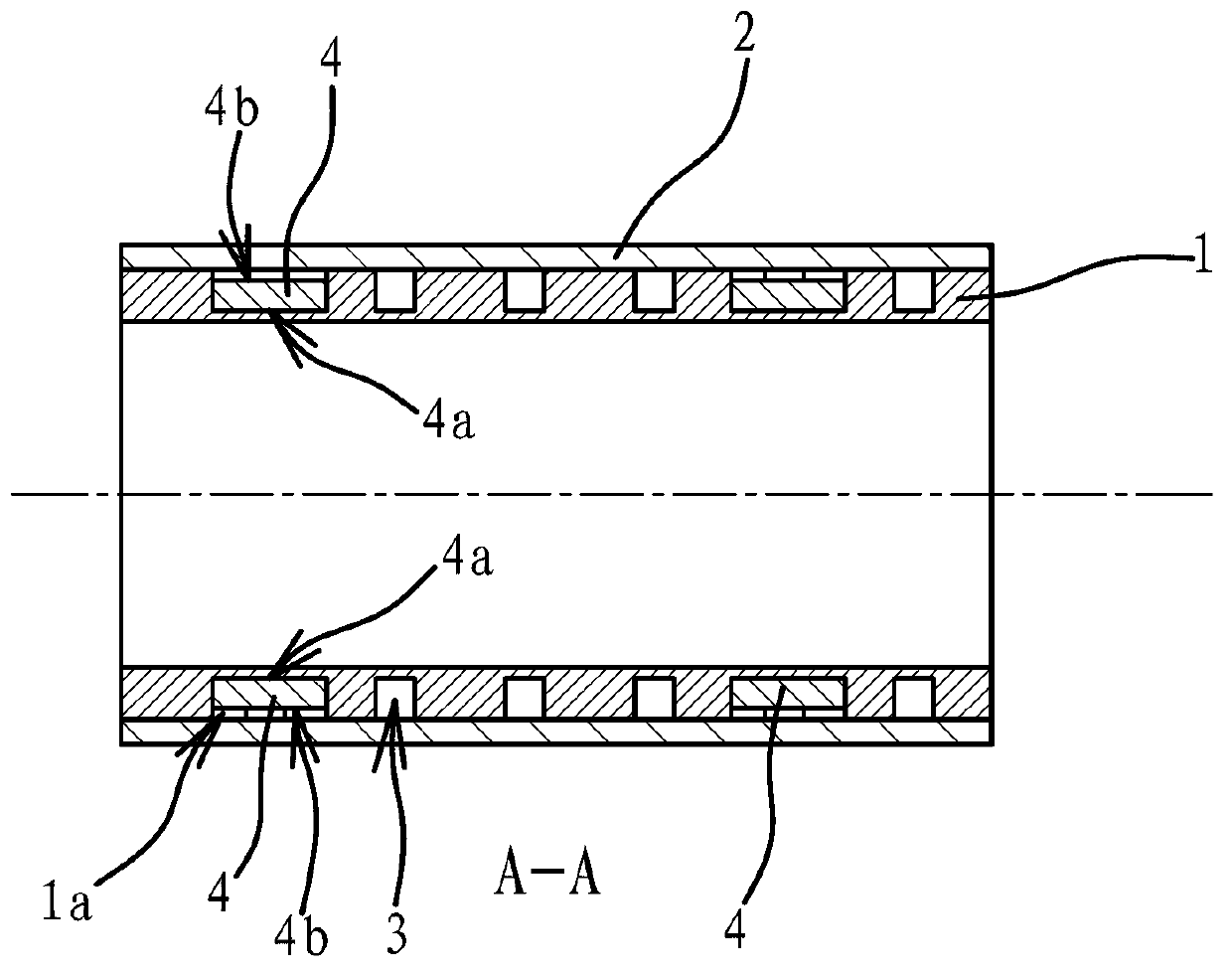
[0036] The structure and principle of this embodiment are basically the same as that of Embodiment 1, the difference is that: Figure 4 As shown, the semiconductive cooling sheet 4 is arc-shaped, and the arc of the semiconducting cooling sheet 4 matches the arc surface of the outer wall of the inner tube 1 . The semiconductor refrigerating sheet 4 is arc-shaped and the arc surface of the outer wall of the inner cylinder 1 matches, so that the semiconductor refrigerating sheet 4 and the outer wall of the inner cylinder 1 can be closely attached, and has the advantage of better heat dissipation.
Login to View More PUM
 Abstract
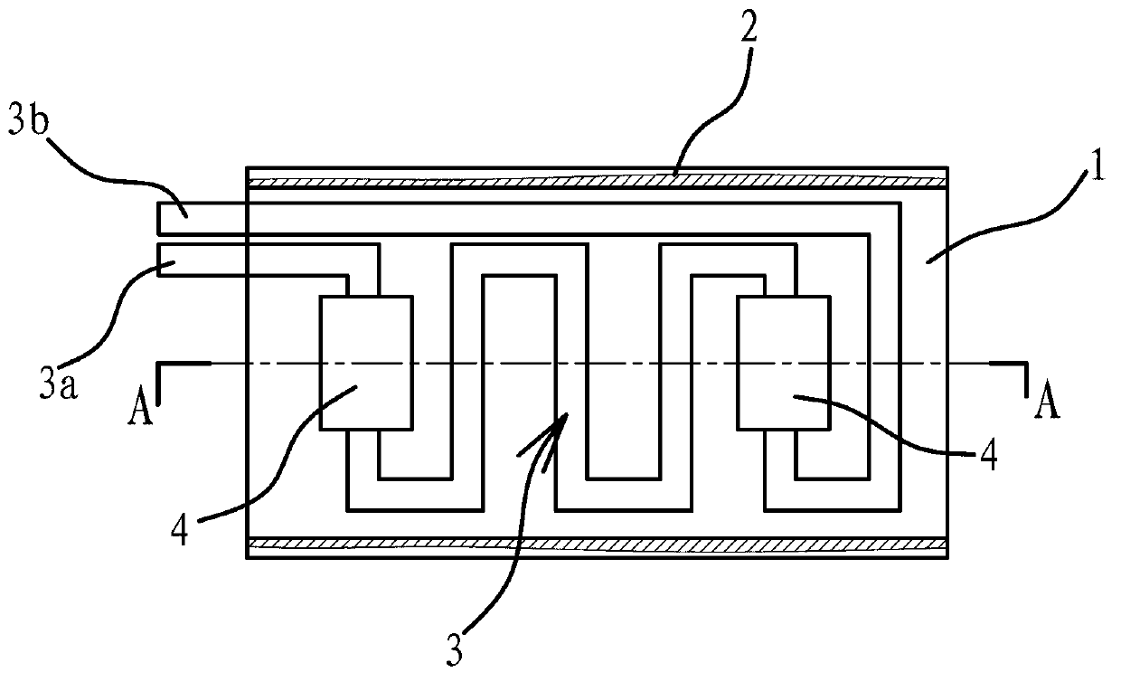
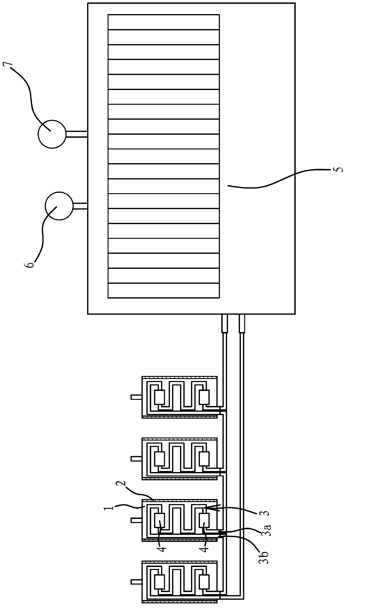
The invention provides a high-speed main shaft cooling device and belongs to the technical field of machinery. The problem that an existing main shaft cooling device is bad in cooling effect is solved. The high-speed main shaft cooling device comprises an inner barrel and an outer barrel which is sleeved on the outer side of the inner barrel. A cooling channel for Freon to flow through is formed between the outer side wall of the inner barrel and the inner side wall of the outer barrel. The cooling channel comprises an inlet and an outlet. A semiconductor cooling piece is arranged between the inner barrel and the outer barrel. A cold face of the semiconductor cooling piece is attached with the outer wall of the inner barrel. A hot face of the semiconductor cooling piece is placed in the cooling channel. The high-speed main shaft cooling device has the advantages that cooling effect is good, so that a high-speed main shaft is long in service life.
Description
technical field [0001] The invention belongs to the technical field of machinery, and relates to a high-speed spindle, in particular to a cooling device for a high-speed spindle. Background technique [0002] A high-speed spindle usually refers to a motor with a speed exceeding 10,000r / min. They have the following advantages: First, due to the high speed, the power density of the motor is high, and the volume is much smaller than that of ordinary motors, which can effectively save materials. Second, it can be connected with the prime mover, [0003] The traditional deceleration mechanism is canceled, the transmission efficiency is high, and the noise is low. Third, due to the small moment of inertia of the high-speed spindle, the dynamic response is fast. [0004] The existing high-speed spindle is mainly cooled by adding coolant to the spindle housing and circulating it continuously to take away the heat. The basic cooling route is: first, the coolant flows out from the...
Claims
Login to View More Application Information
Patent Timeline
 Patent Type & AuthorityApplications(China)
IPC IPC(8): B23Q11/12
Inventor高泉正
Owner玉环三丰阀门股份有限公司