Steel member splicing pretensioner and method for connecting component elements with pretensioner

A technology of pretensioners and steel components, applied in the direction of workpiece clamping devices, hand-held tools, manufacturing tools, etc., to achieve the effect of simple structure, convenient operation, and easy disassembly and assembly

Active Publication Date: 2013-10-09
YELLOW RIVER ENG CONSULTING
View PDF5 Cites 4 Cited by
  • Summary
  • Abstract
  • Description
  • Claims
  • Application Information

AI Technical Summary

Problems solved by technology

[0004] The purpose of the present invention is to provide a steel member splicing pretensioner with simple structure, strong versatility, convenient operation and reusability. At the same time, the present invention also provides a method for using the pretensioner to connect sub-components to solve the problem of large-scale steel structure. Installation and transportation between equipment sub-components

Method used


Image

  • Steel member splicing pretensioner and method for connecting component elements with pretensioner
  • Steel member splicing pretensioner and method for connecting component elements with pretensioner
  • Steel member splicing pretensioner and method for connecting component elements with pretensioner

Examples


Embodiment Construction

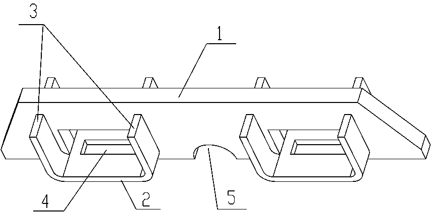
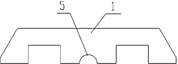
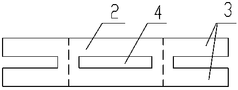
[0025] Such as figure 1 , 2 , 3, the splicing pretensioner for steel members according to the present invention includes trapezoidal plate-shaped keels 1 with rectangular arch grooves at intervals arranged vertically below, horizontally clamped between the rectangular arch grooves of the plate-shaped keels 1 The fixed plate 2, the lower bottom surface of the fixed plate 2 and the plate-shaped keel 1 are located on the same plane; the two pairs of supporting side plates 3 extending upward from the sides of the fixed plate 2 along the plate-shaped keel 1 are respectively connected to the two sides of the plate-shaped keel 1. The side is fixedly connected (welded), and a rectangular through hole is formed between the upper surface of the fixed plate, the two sides of the rectangular arch groove and the top surface; a fixed through groove 4 is opened on the fixed plate corresponding to the position of the rectangular through hole, and the plate-shaped keel 1. A semicircular notch...


PUM


Abstract

The invention discloses a steel member splicing pretensioner which comprises a plate-shaped keel. The plate-shaped keel is longitudinally arranged. Rectangular arch grooves are formed in the lower portion of the plate-shaped keel. Fixing plates are horizontally clamped between the rectangular arch grooves of the plate-shaped keel. Two pairs of supporting side plates which are arranged upwards in an extending mode on the side faces of the plate-shaped keel on two side edges of the fixing plates are respectively and fixedly connected with two side faces of the plate-shaped keel. Rectangular through holes are defined by the upper surfaces of the fixing plates and two sides faces and the top faces of the rectangular arch grooves. Fixing through grooves are formed in the positions, corresponding to the rectangular through holes, of the fixing plates. The steel member splicing pretensioner has the advantages of being simple in structure, convenient to operate, strong in universality and capable of being used repeatedly. Meanwhile, the invention further provides a method for connecting component elements with the pretensioner, two thin elements (such as steel sheets) can be connected, and meanwhile the thicknesses and the directions of the component elements are not limited, and the problems of assembling, separating, lifting and the like of the component elements in a large steel structure equipment manufacturing industry are solved.

Description

technical field [0001] The invention relates to an auxiliary device for manufacturing and installing large-scale equipment, in particular to a splicing pretensioner for steel components, and also relates to a method for connecting subcomponents using the pretensioner. Background technique [0002] During the manufacture and installation of large-scale steel structure equipment, it is generally necessary to decompose the overall equipment into several sub-components to facilitate hoisting and transportation. After the sub-components are manufactured, the sub-components are assembled into a whole, and the relevant test data and functional parameters are obtained through debugging. When the equipment needs to be transported to other places, the overall equipment needs to be disassembled and transported in sub-component units. [0003] At present, temporary welding or bolt connection is generally used to solve the assembly of sub-components in the manufacture of large-scale ste...

Claims


Application Information

Patent Timeline
Patent Type & Authority Applications(China)
IPC IPC(8): B25B11/02B25B27/00
Inventor 乔为民
Owner YELLOW RIVER ENG CONSULTING
Why Eureka
Try Eureka