Loop heat pipe with wick passageways and heat transmission method and manufacturing method thereof

A technology of loop heat pipe and manufacturing method, which is applied in the direction of indirect heat exchangers, lighting and heating equipment, etc., and can solve the problem that loop heat pipes cannot be widely used, air-cooled heat dissipation cannot meet heat dissipation requirements, and limit the application field of loop heat pipes and other problems, to achieve the effect of superior heat transfer performance, superior performance, and reduced thermal resistance

Active Publication Date: 2013-10-09
SOUTH CHINA UNIV OF TECH
View PDF5 Cites 30 Cited by
  • Summary
  • Abstract
  • Description
  • Claims
  • Application Information

AI Technical Summary

Problems solved by technology

In recent years, due to the birth of high heat flux components, equipment, etc., traditional air-cooled heat dissipation has reached the heat dissipation limit and is far from meeting the heat dissipation requirements. Liquid-cooled heat dissipation has also been difficult due to its high cost, complex system, and leakage. widely used
Due to the above reasons, the traditional loop heat pipe can solve the heat dissipation problem, and most of them adopt the horizontal mode and the gravity-assisted mode, while the loop heat pipe in the anti-gravity mode, especially the long-distance anti-gravity mode loop heat pipe is difficult to be applied, which also It will seriously limit the application field of the loop heat pipe, so that the loop heat pipe cannot be widely used

Method used


Image

  • Loop heat pipe with wick passageways and heat transmission method and manufacturing method thereof
  • Loop heat pipe with wick passageways and heat transmission method and manufacturing method thereof
  • Loop heat pipe with wick passageways and heat transmission method and manufacturing method thereof

Examples


Embodiment 1

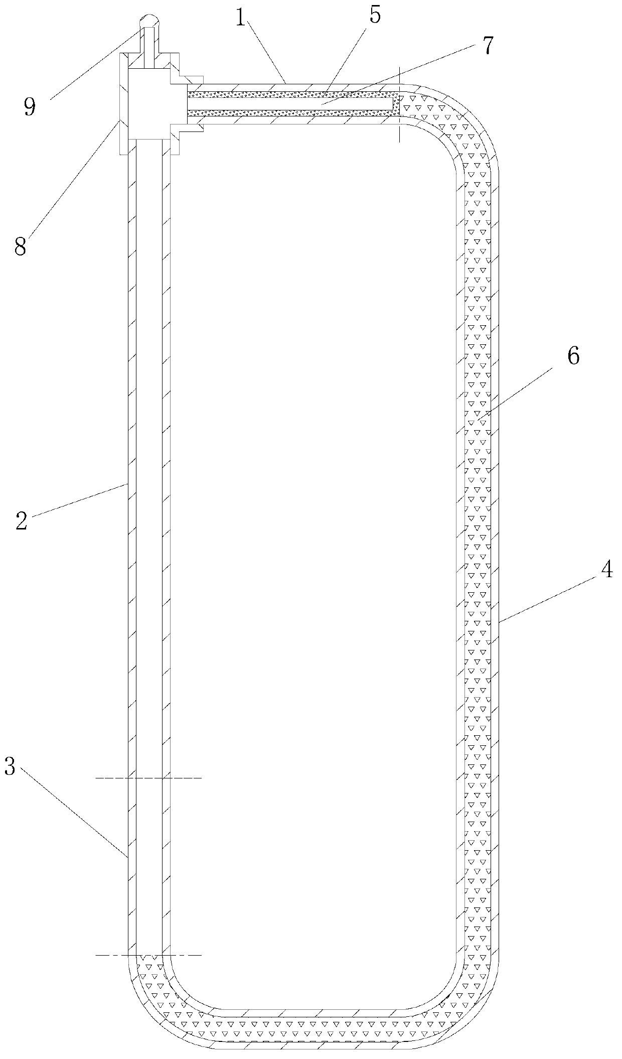
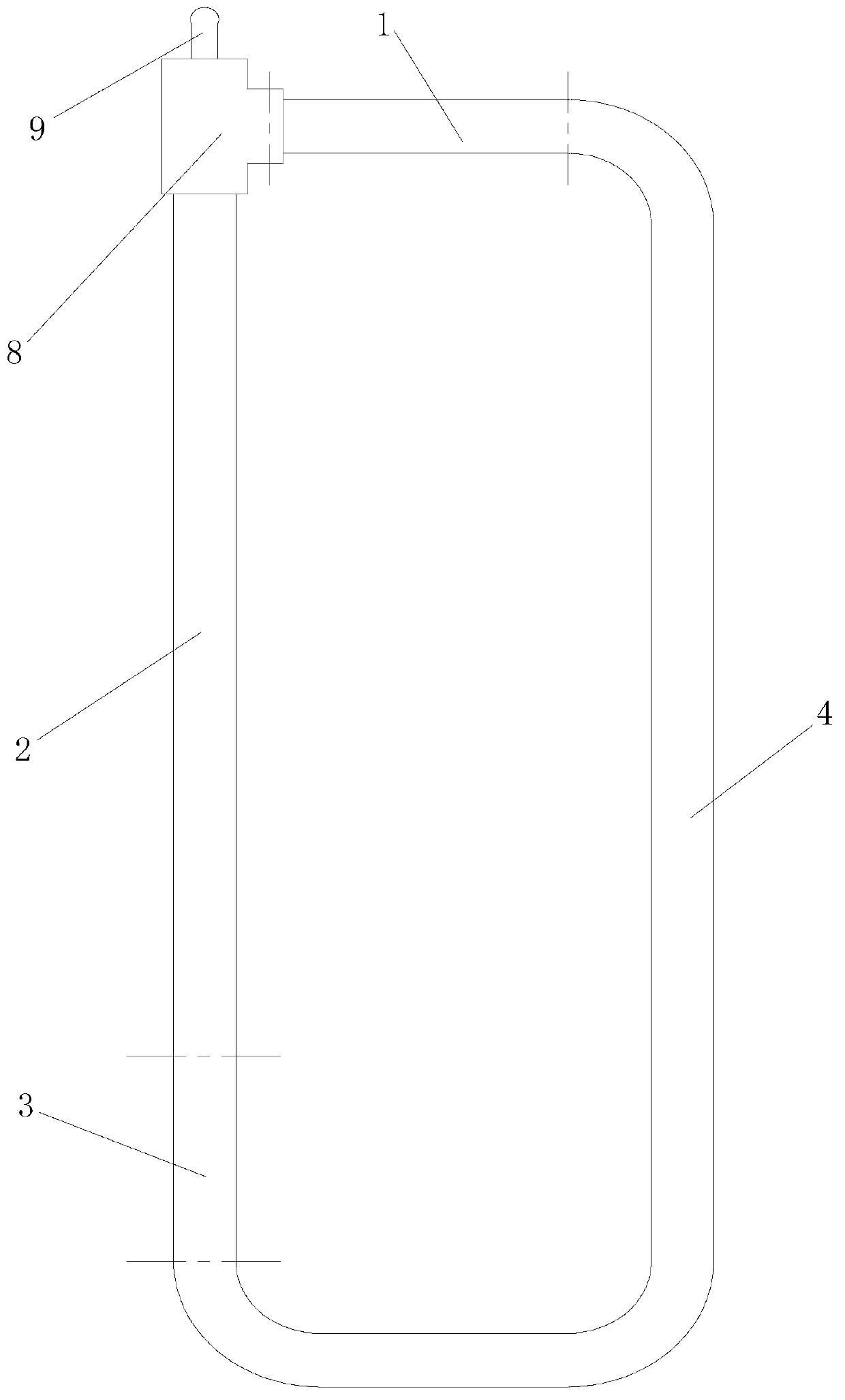
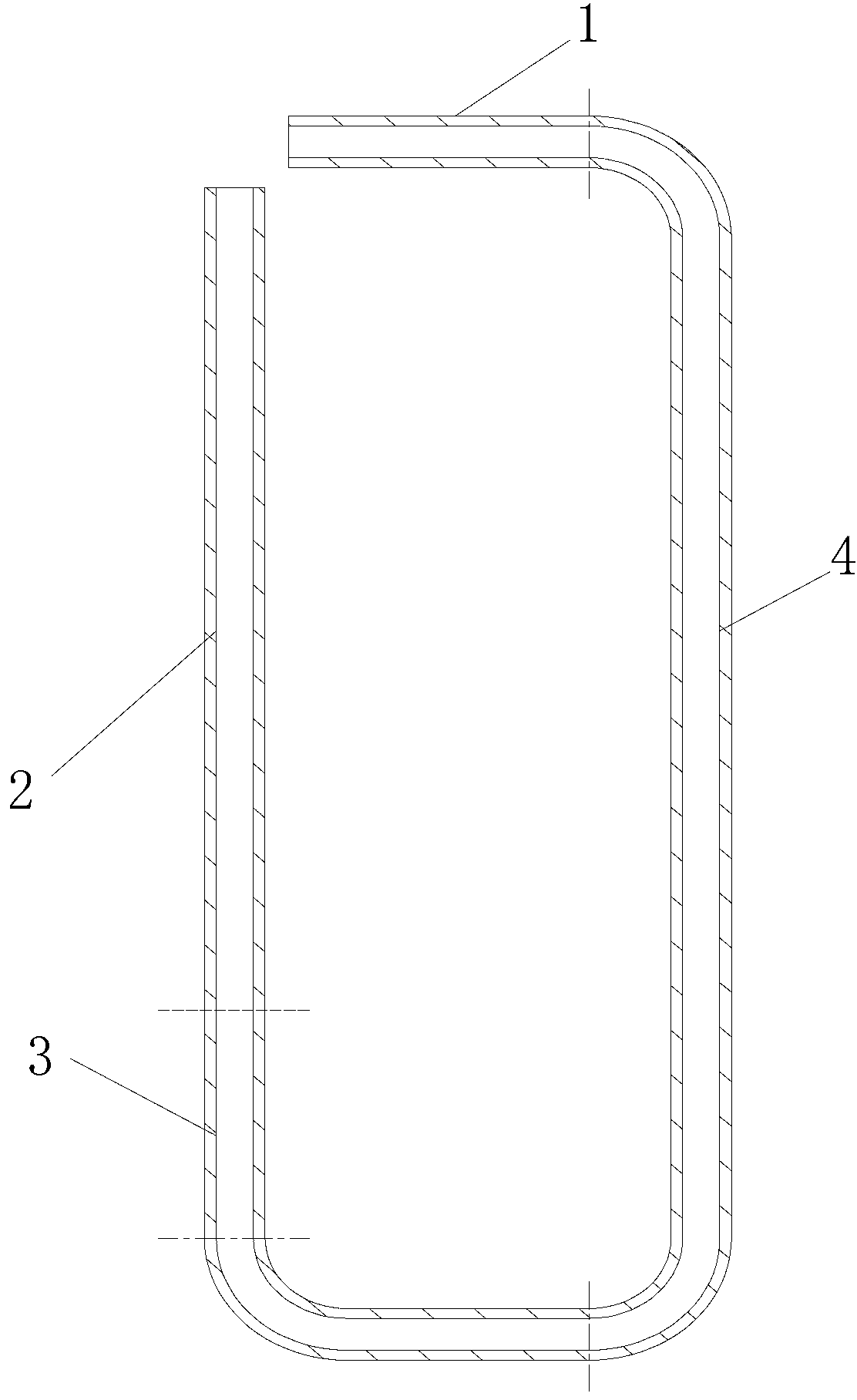
[0030] Such as figure 1 and figure 2 A loop heat pipe shown with a liquid-absorbing wick flow path includes an evaporation section 1, an adiabatic section 2, a condensation section 3, and a liquid infusion section 4 that are sequentially connected end to end to form a loop. The evaporation section 1 and the liquid infusion section 4 The tube body is filled with sintered metal powder, the tube body of the evaporation section 1 and the metal powder form the first liquid-absorbing wick flow channel 5, and the tube body and the metal powder of the infusion section 4 form the second liquid-absorbing wick flow Road 6.

[0031] A round hole 7 concentric with the tube body of the evaporating section 1 is provided in the first liquid-absorbing wick flow channel 6 , and the round hole 7 communicates with the heat insulating section 2 .

[0032] The thickness of the first liquid-absorbing wick channel 5 between the circular hole 7 and the tube body of the evaporation section 1 is 1 mm...

Embodiment 2

[0049] This loop heat pipe with a liquid-absorbing wick flow path is the same as Embodiment 1 except for the following technical features: the thickness of the first liquid-absorbing wick flow path 5 between the circular hole 7 and the tube body of the evaporation section 1 is 0.5 mm.


PUM


Abstract

The invention discloses a loop heat pipe with wick passageways. The loop heat pipe with the wick passageways comprises an evaporation section, a heat insulation section, a condensation section and an infusion section, wherein the evaporation section, the heat insulation section, the condensation section and the infusion section are connected in sequence in an end-to-end mode to form a loop, the pipe body is filled with metal powder at the evaporation section and the infusion section and high sintering is carried out on the metal powder, a first wick passageway is formed by the pipe body at the evaporation section and the metal powder, and a second wick passageway is formed by the pipe body at the infusion section and the metal powder. According to the loop heat pipe with the wick passageways, liquid working media can still move fast under the condition of antigravity through capillary force in the first wick passageway and in the second wick passageway, and therefore heat transmission efficiency is improved, and operating temperature and heat resistance are reduced. The invention further provides a heat transmission method and a manufacturing method of the loop heat pipe with the wick passageways.

Description

technical field [0001] The invention relates to heat transfer equipment technology, in particular to a loop heat pipe with a liquid-absorbing core flow channel, a heat transfer method and a manufacturing method thereof. Background technique [0002] With the rapid development of industries such as the electronics industry, aerospace industry, and equipment manufacturing industry, modern industries have higher and higher requirements for heat dissipation. In recent years, due to the birth of high heat flux components, equipment, etc., traditional air-cooled heat dissipation has reached the heat dissipation limit and is far from meeting the heat dissipation requirements. Liquid-cooled heat dissipation has also been difficult due to its high cost, complex system, and leakage. be widely applied. As an efficient phase change heat transfer device, the loop heat pipe mainly transfers heat through the two-phase change of the heat transfer working medium, and it is becoming more and...

Claims


Application Information

Patent Timeline
Patent Type & Authority Applications(China)
IPC IPC(8): F28D15/04B22F5/12
Inventor 汤勇陆龙生万珍平袁伟李炳林李辉
Owner SOUTH CHINA UNIV OF TECH
Why Eureka
Try Eureka