Phase calibration and correction method for mechanical impedance measurement
A mechanical impedance and phase calibration technology, which is applied in the direction of measuring device, measuring mechanical impedance, measuring ultrasonic/sonic wave/infrasonic wave, etc., can solve the problems of mechanical impedance characteristic deviation, affecting loss factor, restricting the improvement of elastic element design technology, etc. , to achieve the effect of reducing the phase deviation and reducing the error
- Summary
- Abstract
- Description
- Claims
- Application Information
AI Technical Summary
Problems solved by technology
Method used
Image

Examples
specific Embodiment
[0066] The specific embodiment of the inventive method is as follows:
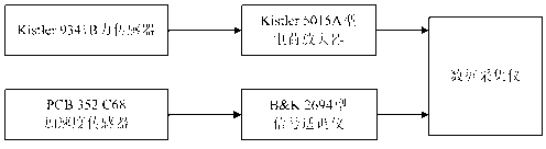
[0067] Taking the mechanical impedance test of the BM300 vibration isolator as an example, two sets of measurement systems are used for measurement. Such as image 3 As shown, the first mechanical impedance measurement system uses 9341B force sensor, 5015A charge amplifier, 352C68 acceleration sensor, 2694 signal conditioner and data acquisition instrument for measurement, as shown in Figure 4 As shown, the second mechanical impedance measurement system uses ICP-type 288D01 impedance head and 2694 signal conditioner, and 2694-type signal conditioner and data acquisition instrument for measurement.
[0068] Such as Figure 5 to Figure 8 As shown, the axial input mechanical impedance test results of the vibration isolator under no-load conditions measured by two different measurement systems, where Figure 8 There is a clear difference in the phase characteristics of the mechanical impedance of the Fig...
PUM
 Abstract
Description
Claims
Application Information