Multi-load wireless energy transmission device capable of automatically controlling

A wireless energy transmission, wireless energy technology, applied in circuit devices, electrical components, electromagnetic wave systems, etc., to improve the degree of charging automation, improve efficiency, and achieve the effect of directional energy flow

Active Publication Date: 2013-10-09
HARBIN INST OF TECH
View PDF5 Cites 10 Cited by
  • Summary
  • Abstract
  • Description
  • Claims
  • Application Information

AI Technical Summary

Problems solved by technology

[0005] The purpose of the present invention is to solve the problem that the existing fixed structure can only selectively charge the loads that need to be charged, and provides a multi-load wireless energy transmission device that can be automatically controlled

Method used


Image

  • Multi-load wireless energy transmission device capable of automatically controlling
  • Multi-load wireless energy transmission device capable of automatically controlling
  • Multi-load wireless energy transmission device capable of automatically controlling

Examples


specific Embodiment approach 1

[0019] Specific implementation mode one: the following combination figure 1 Describe this embodiment, the multi-load wireless energy transmission device capable of automatic control described in this embodiment, it includes an energy transmitting device 1 and N energy receiving devices 2, the electrical signal input end of the energy transmitting device 1 is used to connect an external power supply 3. The electrical signal output ends of N energy receiving devices 2 are respectively connected to the electrical signal input ends of N loads 4, and the energy transmitting device 1 and N energy receiving devices 2 are connected wirelessly through coupling;

[0020] The energy transmitting device 1 includes a transmitting end converter 11 and a wireless energy transmitting circuit 12, the electrical signal input end of the transmitting end converter 11 is used to connect the external power supply 3, and the electrical signal output end of the transmitting end converter 11 is connect...

specific Embodiment approach 2

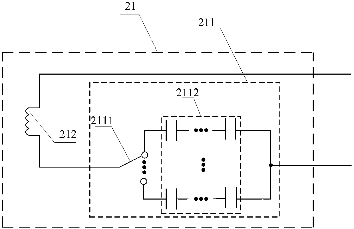
[0026] Specific implementation mode two: the following combination figure 2 Describe this embodiment mode. This embodiment mode will further describe Embodiment 1. The receiving end capacitance device 211 includes a first branch selector 2111 and a capacitance control circuit 2112. The first branch selector 2111 and the capacitance control circuit 2112 are connected in series. On the electrical signal output end of the receiving end capacitance device 211, the capacitance control circuit 2112 includes N capacitance branches, the N capacitance branches are connected in parallel, and the control signal output end of the controller 5 is used to connect the first branch Selector 2111.

[0027] In this embodiment, the first branch selector 2111 selects different capacitance branches to change the capacitance of the receiving end capacitance device 211, thereby changing the resonant frequency of the energy receiving device 2, so that the resonant frequency of the energy transmittin...

specific Embodiment approach 3

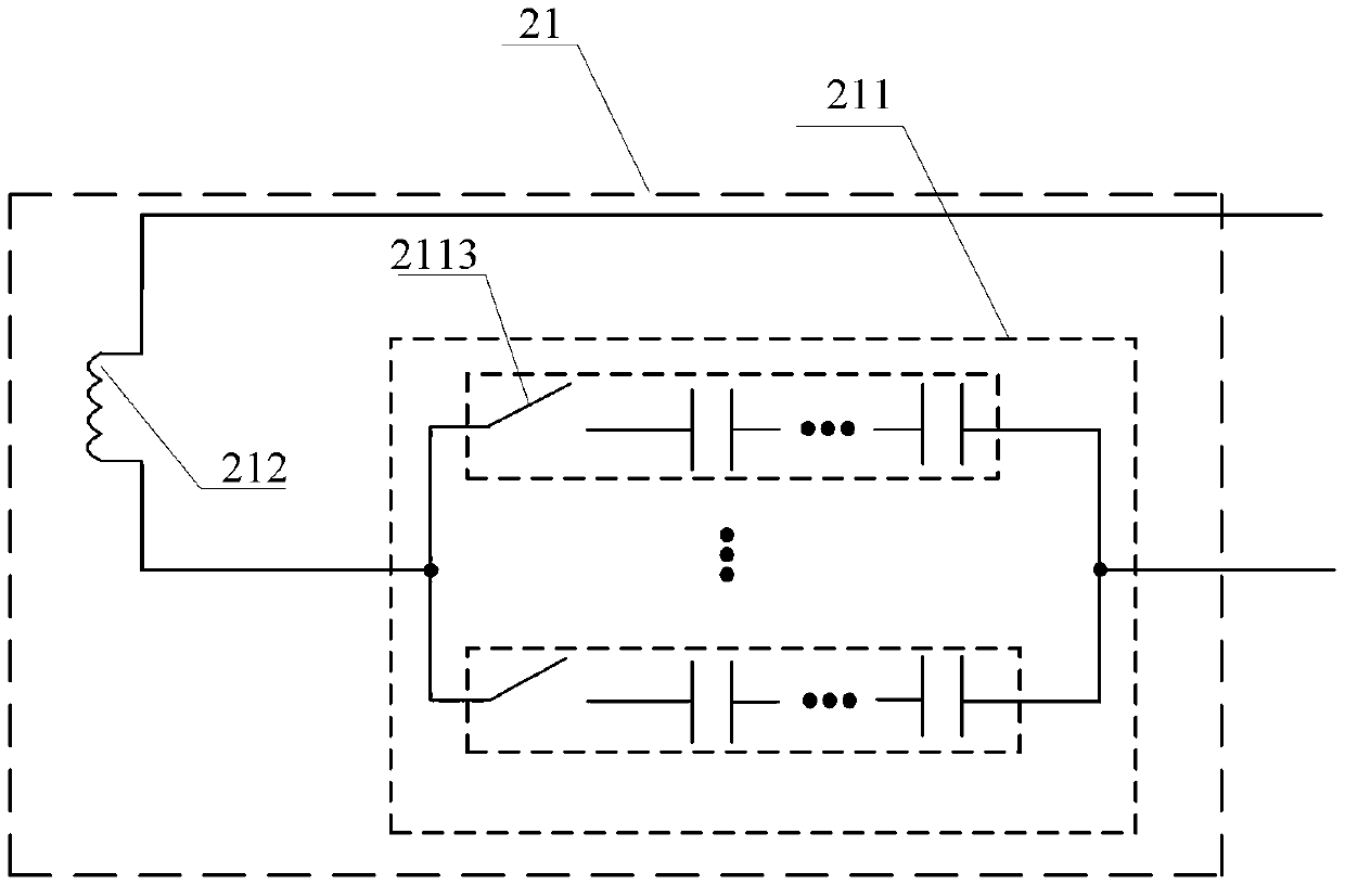
[0028] Specific implementation mode three: the following combination figure 2 This embodiment is described, and this embodiment further describes the second embodiment, the first branch selector 2111 is a single-pole multi-throw switch.


PUM


Abstract

The invention provides a multi-load wireless energy transmission device capable of automatically controlling and belongs to the field of wireless energy transmission, and the device can be used for solving the problem that an existing fixing structure can only selectively supply power to the load which is designated to be charged. The device comprises an energy transmission device and N energy receiving devices, wherein the electric signal input end of the transmission device is used for being connected with an external power supply; the electric signal output ends of the N energy receiving devices are respectively connected with the electric signal input ends of N loads; the transmission device and the N energy receiving devices are in wireless connection in a coupling manner; each energy receiving device comprises a transmission terminal converter and a wireless energy transmission circuit; each energy receiving device comprises a wireless energy receiving module and a receiving terminal converter, and the wireless energy receiving module comprises a capacitance device and an inductance device; each inductance device comprises a branch selector and an inductance control circuit; the inductance control circuit comprises N inductance branches. The multi-load wireless energy transmission device is used in a load charging system of a single-energy transmission terminal and a multi-energy receiving terminal.

Description

technical field [0001] The invention relates to a multi-load wireless energy transmission device capable of automatic control, belonging to the field of wireless energy transmission. Background technique [0002] Wireless energy transmission overcomes the unsafe, aging, and inconvenient problems brought about by traditional wired plug-in charging. Wireless energy transmission has a wide range of applications, such as in the fields of electric vehicle battery charging, home appliance charging, and smart trucks, which greatly improves the level of automation and intelligence. [0003] With the development of wireless energy transfer technology, the multi-load wireless energy transfer system, that is, the single energy transmitter and multi-energy receiver system can meet the demand for charging multiple loads. However, according to the principle of resonance, when the energy transmitter and the energy When the receiver circuit is fixed, the resonant frequency is fixed accordi...

Claims


Application Information

Patent Timeline
Patent Type & Authority Applications(China)
IPC IPC(8): H02J17/00H02J50/10
Inventor 朱春波张剑韬宋凯魏国逯仁贵
Owner HARBIN INST OF TECH
Why Eureka
Try Eureka