Matching type charge pump circuit for phase-locked loop

A charge pump and phase-locked loop technology, applied in the field of matched charge pump circuits, can solve the problems that the circuit matching characteristics cannot reach the matching state, and it is difficult to achieve perfect matching, etc., to achieve a wide swing range, improve output impedance, reduce The effect of switching current glitch effect

Active Publication Date: 2013-10-09
CHENGDU GANIDE TECH
View PDF8 Cites 14 Cited by
  • Summary
  • Abstract
  • Description
  • Claims
  • Application Information

AI Technical Summary

Problems solved by technology

[0004] However, the actual structure of the common charge pump circuit has various non-ideal effects such as clock feedthrough and charge sharing. It is difficult to achieve a perfect match between the pull-up current and sink current of the charge pump under ideal conditions, and the circuit matching characteristics are far from reaching ideal match

Method used


Image

  • Matching type charge pump circuit for phase-locked loop
  • Matching type charge pump circuit for phase-locked loop
  • Matching type charge pump circuit for phase-locked loop

Examples


Embodiment Construction

[0028] The present invention will be described in detail below in conjunction with the accompanying drawings and embodiments, but they are not further limitations on the present invention.

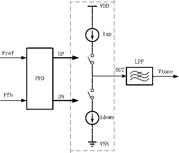
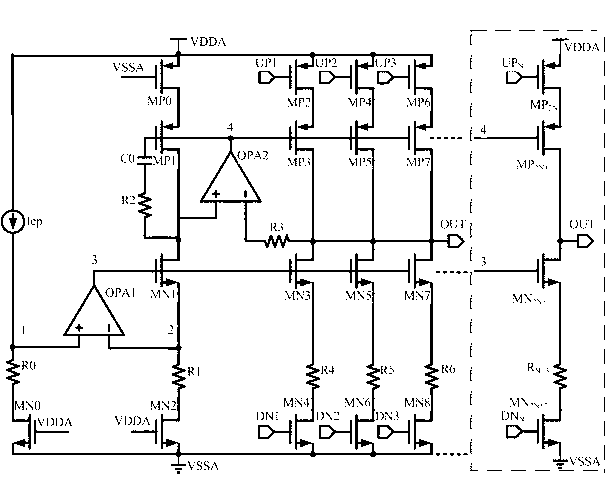
[0029] Such as figure 2 As shown, the matching charge pump circuit for the phase-locked loop disclosed by the present invention includes a proportional bias circuit, a current replication circuit, a sinking constant current source circuit, a pull-up constant current source circuit and a switch circuit; wherein,

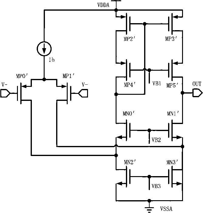
[0030] The proportional bias circuit is used to amplify the external reference current proportionally to generate the bias current required by the charge pump circuit. The proportional bias circuit is composed of the first operational amplifier OPA1 and a negative feedback circuit; the input of the proportional bias circuit The terminal is connected to the power supply; the output terminal of the proportional bias circuit is connected to the input terminal of the current replicat...


PUM


Abstract

The invention discloses a matching type charge pump circuit for a phase-locked loop. The matching type charge pump circuit comprises an in-proportion bias circuit, a current duplication circuit, a sunk constant-current source circuit, a pull-up constant-current circuit and a switch circuit. The in-proportion bias circuit magnifies an external reference current proportionally. The current duplication circuit strictly duplicates a current in an NMOS current mirror for a PMOS current mirror. The sunk constant-current source is used for discharging a later-stage load. The pull-up constant-current circuit is used for charging the later-stage load. The switch circuit is used for controlling switching-on and switching-off of a charge-discharge current source. According to the matching type charge pump circuit for the phase-locked loop, the bias current mirror image proportion of the in-proportion bias circuit depends on the ratio of resistance values of a resistor R0 and a resistor R1. The matching type charge pump circuit for the phase-locked loop is more reliable in structure compared with a traditional structure and is not affected by technology angles and temperature variation so as to accurately control loop parameters of the phase-locked loop of a charge pump, and the charge sharing effect existing in common charge pump design is well eliminated.

Description

technical field [0001] The invention relates to a charge pump phase-locked loop (CPPLL), in particular to a matching charge pump circuit for the phase-locked loop, which realizes high matching of the circuit and can significantly reduce the phase noise of the phase-locked loop system. Background technique [0002] CMOS charge pump phase-locked loop circuit (Charge Pump Phase-locked Loop, CPPLL) has the advantages of high speed, low power consumption, low jitter, low cost and easy integration, and is widely used in frequency synthesis, clock recovery and other circuits. As a key module in the phase-locked loop of the charge pump, the current matching characteristic of the charge pump circuit is directly related to the near-end phase noise performance of the CPPLL. How to further improve the current matching characteristics of the charge pump has always been the focus of charge pump design and research. [0003] An ideal charge pump structure such as figure 1 As shown, its f...

Claims


Application Information

Patent Timeline
Patent Type & Authority Applications(China)
IPC IPC(8): H03L7/08
Inventor 李东明陈普锋童伟吕继平胡柳林苏黎
Owner CHENGDU GANIDE TECH
Why Eureka
Try Eureka