Constant-current drive circuit of LED switching power supply

A technology of constant current drive and switching power supply, which is applied in the electronic field, can solve the problems of large deviation and the influence of the constant current performance of the BUCK structure, and achieve the effect of good constant current characteristics

Active Publication Date: 2013-10-09
成都川美新技术股份有限公司
View PDF3 Cites 0 Cited by
  • Summary
  • Abstract
  • Description
  • Claims
  • Application Information

AI Technical Summary

Problems solved by technology

Usually these three parameters have relatively large deviations, so the constant current performance of the BUCK structure is inherently affected by the parameters of these peripheral devices

Method used


Image

  • Constant-current drive circuit of LED switching power supply
  • Constant-current drive circuit of LED switching power supply
  • Constant-current drive circuit of LED switching power supply

Examples


Embodiment Construction

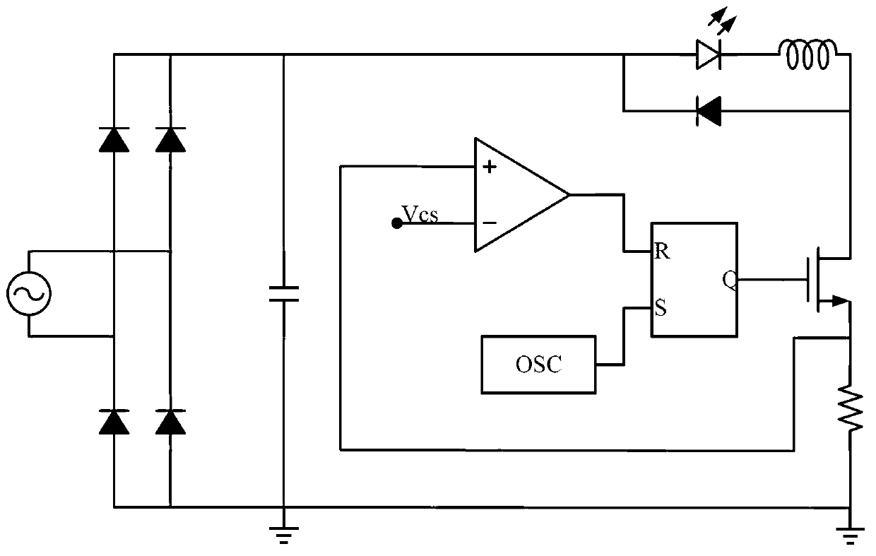
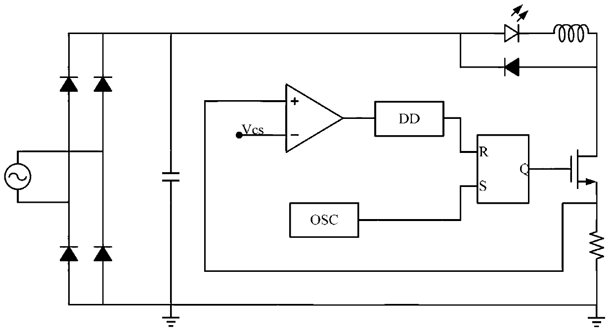
[0020] The LED switching power supply constant current driving circuit of the present invention comprises a rectification and filtering circuit, a power tube, an RS flip-flop, an oscillator and an operational amplifier. The two input ends of the RS flip-flop are respectively connected to the output end of the operational amplifier and the oscillator, and the Q terminal is connected to the The gate of the power tube is characterized in that the operational amplifier is connected to the input end of the RS flip-flop through a delay doubling circuit.

[0021] The delay doubling circuit includes: a first constant current source, a first switching device SW1, a second switching device SW2, and a second constant current source connected in series in sequence, one end of the second constant current source is grounded, and the first switching device SW1 and the second constant current source are connected in series. The connection point of the second switching device SW2 is grounded th...


PUM


Abstract

The invention relates to electronic techniques, and provides a constant-current drive circuit of an LED switching power supply. The constant-current drive circuit comprises a rectification filter circuit, a power tube, an RS flip-flop, an oscillator and an operational amplifier. Two input ends of the RS flip-flop are respectively connected with an output end of the operational amplifier and the oscillator, and a Q end of the RS flip-flop is connected with a grid of the power tube. The constant-current drive circuit of the LED switching power supply is characterized in that the operational amplifier is connected with the input ends of the RS flip-flop through a delay doubling circuit. The constant-current drive circuit of the LED switching power supply has the advantages that the delay doubling circuit is added in a loop circuit compared with an existing BUCK structured constant-current drive circuit, and enables output current to be unrelated to LED voltage, clock periods and intensity of inductance, and therefore the constant-current drive circuit is good in constant-current characteristic.

Description

technical field [0001] The present invention relates to electronic technology, in particular to integrated circuit technology. Background technique [0002] Figure 1a Shown is the BUCK structure constant current drive circuit, Figure 1b For the working waveform diagram. When the inductor current, that is, the LED output current increases to Vcs / Rcs, the output of the comparator is reversed, and a RESET signal is given to the RS flip-flop. The output Q of the RS flip-flop is low level, the power tube is open, and the inductor current drops. The inductor peak current is [0003] Ipeak = Vcs Rcs [0004] After a fixed time Toff, the inductor current (same as the LED current) decreases by [0005] ΔI = Toff L Vout [0006] So there is in constant off-time mode, the output current [0007] I = ...

Claims


Application Information

Patent Timeline
Patent Type & Authority Applications(China)
IPC IPC(8): H05B37/02
Inventor 向本才薛学范李向华
Owner 成都川美新技术股份有限公司
Why Eureka
Try Eureka