Simple conveying mechanism

A transmission mechanism and simple technology, applied in the directions of transportation, packaging, chute, etc., can solve the problems of low work efficiency and high labor intensity, and achieve the effect of avoiding large swing and avoiding damage.

Inactive Publication Date: 2013-10-16
CHENGDU LINGCHUAN SPECIAL IND
View PDF6 Cites 3 Cited by
  • Summary
  • Abstract
  • Description
  • Claims
  • Application Information

AI Technical Summary

Problems solved by technology

[0003] The invention solves the problems of high labor intensity and low work efficiency of workers in the traditional transmission mode by setting a simple transmission mechanism, so as to achieve the purpose of improving work efficiency

Method used


Image

  • Simple conveying mechanism

Examples


Embodiment 1

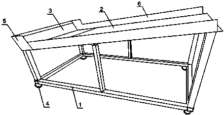
[0020] like figure 1 As shown, this embodiment includes a support frame 1, a transmission plate 2, a baffle plate 5 and a plurality of universal wheels 4, the transmission plate 2 is connected to the baffle plate 5, and the transmission plate 2 and the baffle plate 5 are all arranged on the support frame 1 Above, the universal wheels 4 are evenly distributed on the bottom of the support frame 1, and the connection between the transmission plate 2 and the support frame 1 is also provided with a spring, and also includes a rubber pad 3 arranged on the bottom of the transmission plate 2 and the baffle plate 5. The transmission plate 2 set on the support frame 1 is at a certain angle to the horizontal direction, and the silencer cylinder that has completed the curling process is placed on the top of the transmission plate 2, and slides down to the bottom of the transmission plate 2 under the action of the silencer cylinder’s own gravity , and finally collected by the staff respons...

Embodiment 2

[0024] like figure 1 As shown, this embodiment is based on Embodiment 1, the inclination angle of the transmission plate 2 is 15°-45°, and the transmission plate 2 is provided with anti-slip patterns. Tilting at a certain angle allows the muffler to freely slide downwards to the detection place for detection under the action of gravity; the transmission distance may be long or short, and the anti-skid pattern set on the transmission plate 2 can control the sound of the muffler to a certain extent. Decrease speed, avoid its descending too fast and cause violent collision with baffle plate 5.

Embodiment 3

[0026] like figure 1 As shown, on the basis of Embodiment 1, this embodiment further includes side baffles 6 arranged on both sides of the conveying plate 2 , and the side baffles 6 are vertically connected to the baffles 5 . When the muffler slides down, the rolling track is easy to change. When the transmission distance is long, the muffler will slide out of the transmission plate 2 and fall to the ground causing damage to the muffler. The side baffles 6 on both sides of the transmission plate 2 can limit the sliding track of the muffler to prevent its side Slide out the transfer plate 2.

[0027] Preferably, the rubber pad 3 is styrene-butadiene rubber. Styrene-butadiene rubber (SBR) is a copolymer of styrene and butadiene. Compared with natural rubber, it has uniform quality, less foreign matter, and excellent mechanical stability.

[0028] Preferably, the support frame 1 is made of cast iron.


PUM


Abstract

The invention discloses a simple conveying mechanism. The simple conveying mechanism comprises a supporting frame, a conveying board, a baffle and a plurality of universal wheels, wherein the conveying board is connected with the baffle, both the conveying board and the baffle are arranged on the supporting frame, the universal wheels are evenly distributed on the bottom of the supporting frame, and a spring is arranged at the position where the conveying board is connected with the supporting frame. The simple conveying mechanism further comprises a rubber pad which is arranged on the bottom of the conveying board and on the baffle. A certain angle is formed between the conveying board arranged on the supporting frame and the horizontal direction. A noise reduction barrel is placed at the top end of the conveying board after hemming is carried out on the noise reduction barrel, the noise reduction barrel slides downwards to the bottom end of the conveying board under the self-gravity of the noise reduction barrel, and finally the noise reduction barrel is collected by a worker responsible for detection. According to the simple conveying mechanism, when the noise reduction barrel collides with the baffle, acting force applied to the baffle can be further buffered by the universal wheels arranged on the bottom of the supporting frame and the spring arranged between the supporting frame and the conveying board, the supporting frame is prevented from swinging seriously, and then the internal structure of the noise reduction barrel is prevented from being damaged to a certain degree.

Description

technical field [0001] The invention relates to the field of engine exhaust mufflers, in particular to a simple transmission mechanism. Background technique [0002] The manufacturing process of the automobile muffler is roughly as follows: First, the rolled plate needs to be cut with a shearing machine, cut to a suitable size and rolled into a cylindrical shape with a circular machine; The middle seam is combined with positive and negative bending on both sides, and the lap joint is pressed out with a hydraulic embossing machine. The forming machine can make the cylinder body into various specifications and shapes, such as round, square, oval, triangular, etc.; Both ends of the cylinder body are crimped, and after the crimping is completed, the cylinder body is combined with the covers at both ends; finally, after the cylinder body is manufactured, the exhaust pipe is processed by pipe bending machines, tube expanders, tube shrinkers and other pipe processing equipment. Pr...

Claims


Application Information

Patent Timeline
Patent Type & Authority Applications(China)
IPC IPC(8): B65G11/02B65G11/18
Inventor 杨军张军叶维敏汪庭文何晓鸣
Owner CHENGDU LINGCHUAN SPECIAL IND
Why Eureka
Try Eureka