
Gas-floatation rotational-flow coalescence composite type sewage oil-removing device

A composite, coalescing technology, used in oil/oil/float removal devices, flotation water/sewage treatment, centrifugal separation water/sewage treatment, etc. problems, to achieve the effect of improving the finishing effect, saving investment and stable operation

Inactive Publication Date: 2013-10-16
CHINA OIL HBP SCI & TECH CO LTD +1
View PDF12 Cites 23 Cited by
  • Summary
  • Abstract
  • Description
  • Claims
  • Application Information

AI Technical Summary

Problems solved by technology

[0006] The purpose of the present invention is to provide an air flotation swirl flow coalescence composite sewage degreasing device to solve technical problems such as low efficiency, poor intensification and unstable operation of the swirl air flotation integrated combined degreasing technology equipment

Method used


Image

  • Gas-floatation rotational-flow coalescence composite type sewage oil-removing device
  • Gas-floatation rotational-flow coalescence composite type sewage oil-removing device
  • Gas-floatation rotational-flow coalescence composite type sewage oil-removing device

Examples


Embodiment Construction

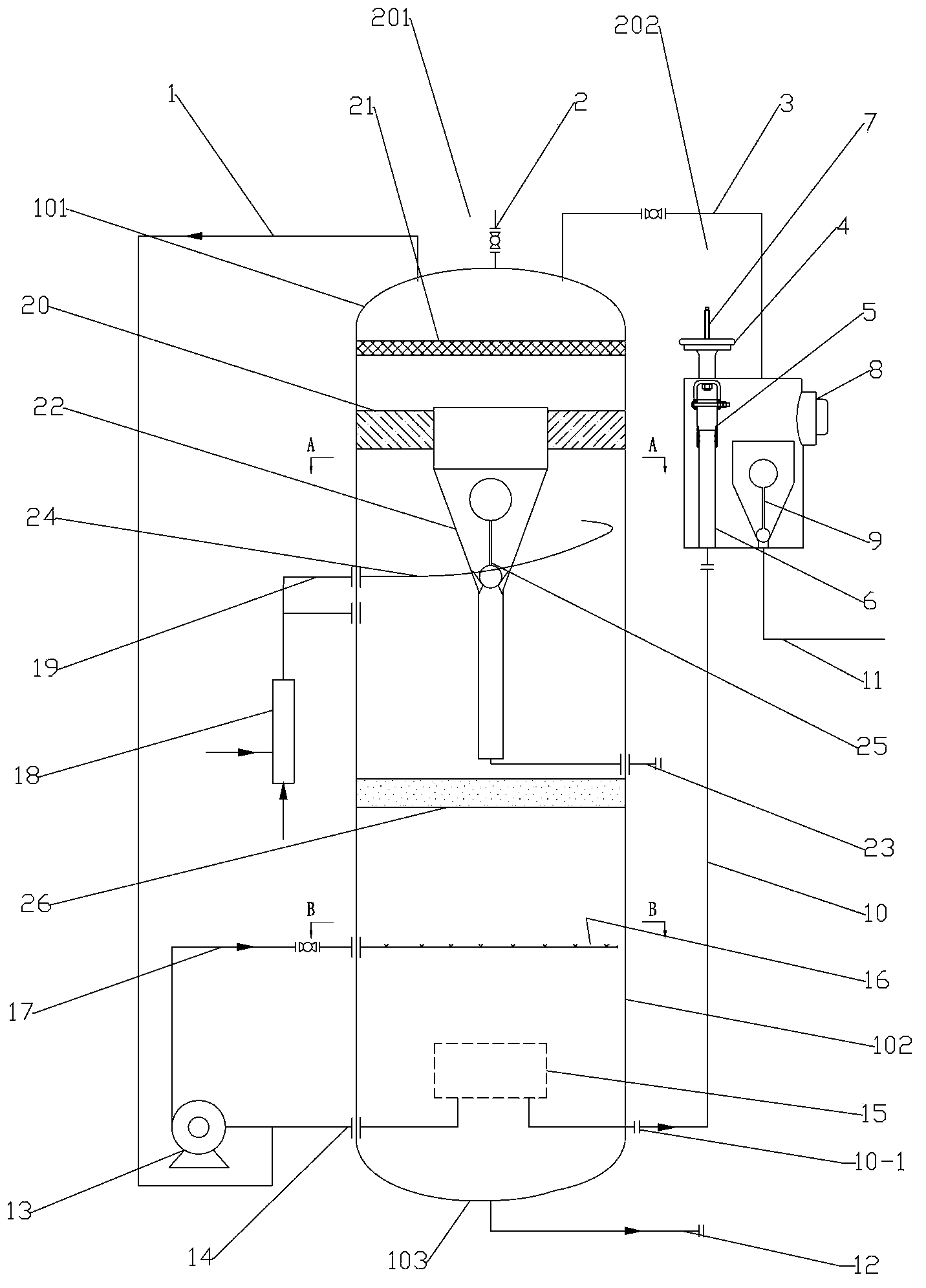
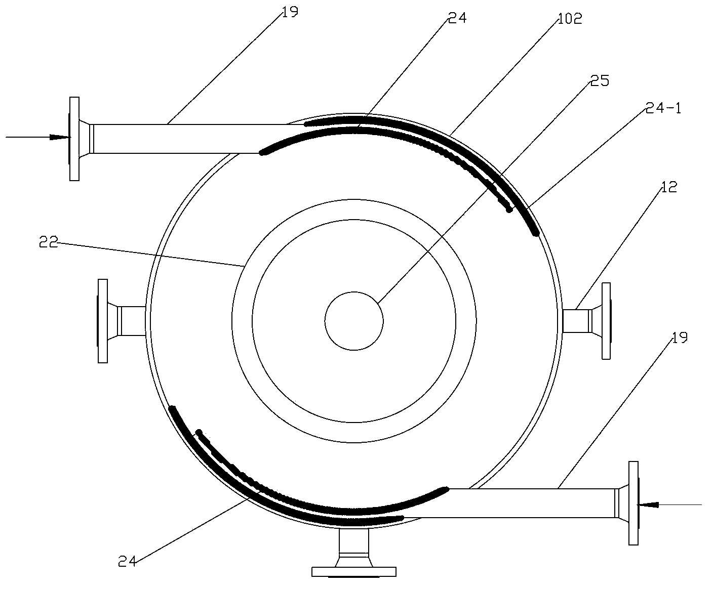
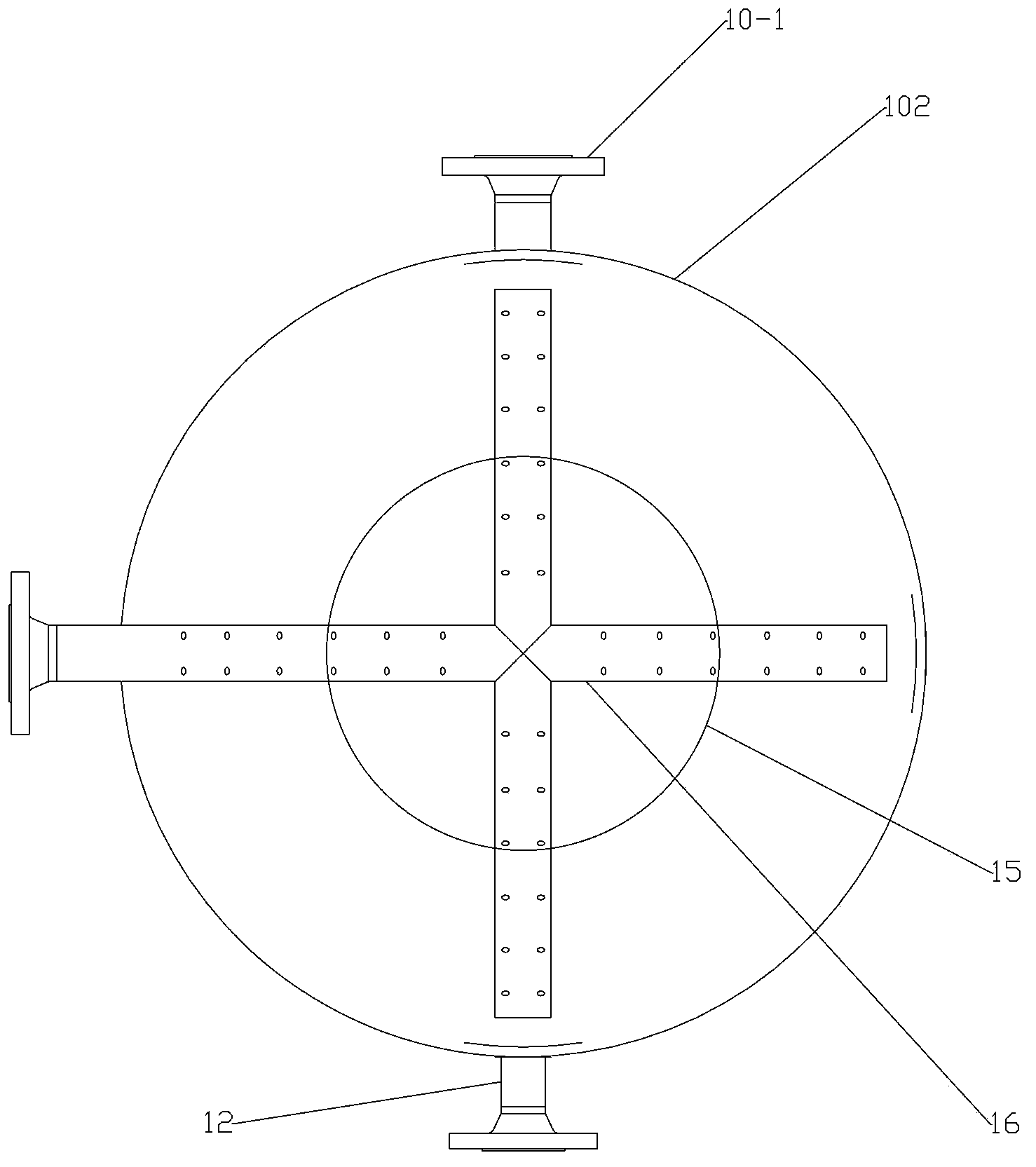
[0024] see Figure 1-Figure 4 , is the implementation example of the air flotation swirl flow coalescence composite sewage deoiling device in the present invention, but the present invention is not limited to the following examples;

[0025] The air flotation swirling flow coalescence composite sewage degreasing device is mainly composed of a multifunctional separation tank 201, a two-stage gas-water mixing device, and an adjustment control box 202; the multifunctional separation tank 201 is a vertical cylindrical tank, which consists of a cylinder body 102, Composed of an upper head 101 and a lower head 103, the upper part of the equipment has a tangential liquid inlet 19, the middle part has an oil outlet 23, the lower part has a circulating water inlet / outlet 17, the bottom has a sewage outlet 12, and the top has a The exhaust port 2 and the connecting pipe 1, 3; the liquid inlet adopts a tangential direction to enter, and the liquid inlet in the tank is provided with a div...


PUM

PropertyMeasurementUnit
aspect ratioaaaaaaaaaa

Abstract

The invention discloses a gas-floatation rotational-flow coalescence composite type sewage oil-removing device. The gas-floatation rotational-flow coalescence composite type sewage oil-removing device mainly comprises a multifunctional separating tank, a two-stage gas-water mixing device and an adjusting and control box, wherein liquid inlets are formed in the middle-upper part of the multifunctional separating tank, an oil outlet is formed in the middle part of the multifunctional separating tank, a water-soluble gas circulation device, a sewage discharging port is formed in the bottom of the multifunctional separating tank, and an gas exhaust port is formed in and a communicating pipe is arranged at the top part of the multifunctional separating tank. The multifunctional separating tank is internally provided with an inner rotational-flow drum, and the bottom of the multifunctional separating tank is connected with an oil outlet pipe. A gas mist catcher is arranged above the inner rotational-flow drum; a water collector at the lower part of the multifunctional separating tank is respectively connected with a water outlet and a circulatign water outlet of the multifunctional separating tank; a gas exhaust port in the top part of the separating tank is connected with an inlet of the two-stage gas-water mixing device by a pipeline. The water outlet of the separating tank is connected with a water inlet of the adjusting and control box at the side, and the top part of the adjusting and control box is communicated with the top part of the separating tank. The gas-floatation rotational-flow coalescence composite type sewage oil-removing device disclosed by the invention has the advantage that the technical problems of low efficiency, poor intensiveness, unstable operation and the like in the rotational-flow gas-floatation integration combined oil-removing technical equipment can be solved.

Description

technical field [0001] The invention relates to a novel integrated cyclone air flotation and coalescence multifunctional oil removal equipment, which is suitable for sewage treatment in oil and gas fields, sewage treatment in petrochemical industry and the like. Background technique [0002] With the improvement of the degree of oilfield exploitation, the exploitation technology is becoming more and more advanced, and the difficulty of water treatment is gradually increasing. At the same time, the development of various marginal oilfields and deep-sea oilfields also puts forward new requirements for water treatment technology. The traditional treatment unit has been It cannot meet the water treatment requirements, and the new oilfield water treatment technology is also developing in the direction of integration, high efficiency and intensification. [0003] At present, the water treatment methods widely used in oil fields are mainly physical separation and chemical agent ass...

Claims


Application Information

Patent Timeline
Patent Type & Authority Applications(China)
IPC IPC(8): C02F1/40C02F1/24C02F1/38
Inventor 孙飞朱智文孙永进
Owner CHINA OIL HBP SCI & TECH CO LTD
Learn More