Electronic back-pulling mechanism

An electronic and tensioning mechanism technology is applied in the field of sewing machines to achieve the effects of convenient maintenance and processing, improved production efficiency and simple structure

Active Publication Date: 2013-10-16
XIAN TYPICAL IND
View PDF9 Cites 14 Cited by
  • Summary
  • Abstract
  • Description
  • Claims
  • Application Information

AI Technical Summary

Problems solved by technology

[0004] This invention provides an electronic back dragging mechanism to overcome the problems of complex structure, poor sewing material feeding and low production efficiency existing in the prior art

Method used


Image

  • Electronic back-pulling mechanism
  • Electronic back-pulling mechanism

Examples


Embodiment Construction

[0020] The present invention will be described in detail below in conjunction with the accompanying drawings.

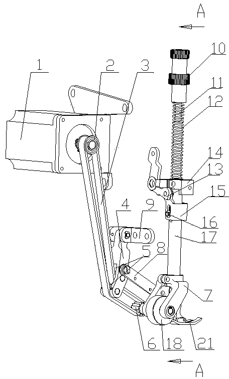
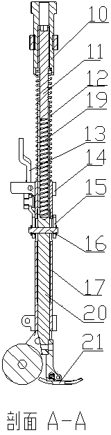
[0021] see figure 1 and figure 2 , an electronic dragging mechanism, including a motor 1, a first synchronous pulley 2, a synchronous belt 3, a second synchronous belt pulley 6, a synchronous belt tensioning mechanism, a mop wheel assembly 18 and a presser foot mechanism, and the mop wheel assembly 18 is Including the tug wheel frame 7, the presser foot mechanism includes an outer pressure adjusting screw assembly 10, an inner compression rod spring 19, an inner compression rod 20 and a presser foot assembly 21 arranged from top to bottom, and the timing belt tensioning mechanism includes A swing rod 4, a pair of needle roller bearing assemblies 5, a connecting rod 8 and a swing rod seat 9, one end of the swing rod 4 is a double-fork structure, and a pair of needle roller bearing assemblies 5 are arranged between the ends of the double-fork structure, A pair ...


PUM


Abstract

The invention relates to the technical field of sewing machines, in particular to an electronic back-pulling mechanism, and solves the problems that the structure is complex, the sewing feeding is unsmooth, and the production efficiency is low in the prior art. The technical scheme is as follows: the electronic back-pulling mechanism comprises a motor, a first synchronous pulley, a second synchronous pulley, a synchronous belt, a synchronous belt tensioning mechanism, a cloth tug component and a presser foot mechanism, wherein one end part of an oscillating bar adopts a double fork structure; the oscillating bar is connected with the synchronous belt, the other end part of the oscillating bar is hinged to an oscillating bar seat; a connecting rod is hinged between the middle of the oscillating bar and a tug rack; an external voltage-regulating screw component adopts an internal thread voltage-regulating structure; an internal voltage-regulating screw rod is in threaded connection with the external voltage-regulating screw; the lower end of the internal voltage-regulating screw rod is pressed onto the upper end of an internal pressing rod spring; the internal pressing rod spring and the internal pressing rod are glidingly sleeved with an external pressing rod; the outer side of the upper part of the external pressing rod is fixedly connected with an upper-raising guide frame; a connecting ring is arranged above the upper-raising guide frame and outside the external pressing rod; and the cloth tug component is fixedly connected with the lower part of the external pressing rod.

Description

Technical field: [0001] The invention relates to the technical field of sewing machines, in particular to an electronic back dragging mechanism. Background technique: [0002] At present, the rear dragging mechanism used by sewing machines is generally a mechanical rear dragging mechanism. To complete a sewing process of dragging cloth backwards in a straight line, the coordinated operation of the mopping wheel mechanism and the presser foot mechanism is required. The commonly used mop wheel mechanism and the presser foot mechanism are separated. The mop wheel mechanism has its own control mechanism for adjusting the pressure. The mop wheel mechanism is mainly composed of two parts: the mop wheel assembly and the drive assembly; Set pressure adjusting screw assembly, compression rod spring, compression rod and presser foot assembly. The problems existing in the prior art are: 1. The mop wheel mechanism and the presser foot mechanism are two sets of independent mechanisms,...

Claims


Application Information

Patent Timeline
Patent Type & Authority Applications(China)
IPC IPC(8): D05B33/00D05B29/06
Inventor 朱寅陈晓宇朱强齐军畅刘永
Owner XIAN TYPICAL IND
Why Eureka
Try Eureka