Roof brushed frame moving valve of hydraulic support for coal mine

A hydraulic support and frame moving technology, which is applied in mine roof support, mining equipment, earthwork drilling and mining, etc., can solve the problems of increasing labor intensity of operators, reducing coal mining efficiency, and caving

Inactive Publication Date: 2013-10-16
郑州煤机液压电控有限公司
View PDF7 Cites 0 Cited by
  • Summary
  • Abstract
  • Description
  • Claims
  • Application Information

AI Technical Summary

Problems solved by technology

For relatively hard roofs, there is no problem with this working cycle method, but for unstable direct roofs, false roofs or geological conditions with broken roofs, such a working cycle process has great potential safety hazards. The main reason is that : The hydraulic support must first lower the column before moving the frame. After the support lowers the column, the unstable direct roof, false roof or broken roof will sink, break, and collapse due to repeated support, resulting in roof leakage or roof fall accidents. Possesses a very large safety threat to underground workers
At the same time, the support must be lowered before the column can be moved, and the operating handles of the two control valves need to be operated in sequence, which increases the labor intensity of the operator and reduces the coal mining efficiency.

Method used


Image

  • Roof brushed frame moving valve of hydraulic support for coal mine
  • Roof brushed frame moving valve of hydraulic support for coal mine
  • Roof brushed frame moving valve of hydraulic support for coal mine

Examples


Embodiment Construction

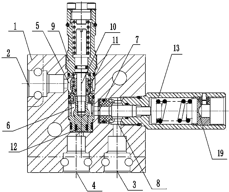
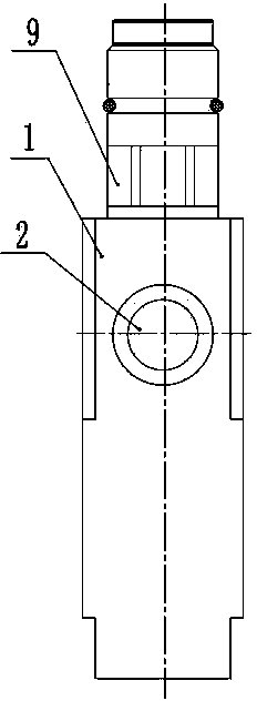
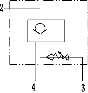
[0012] Such as figure 1 , 2 As shown, the coal mine hydraulic support wiping top moving valve according to the present invention includes a valve body 1, a high-pressure liquid inlet 2, a liquid return port 3, and a control liquid port 4 provided on the valve body 1; The valve body 1 is provided with a hydraulically controlled check valve and a check valve 13; the working chamber 5 of the hydraulically controlled check valve communicates with the high-pressure liquid inlet 2, and the unloading chamber 6 of the hydraulically controlled check valve communicates with the The liquid inlet 7 of the one-way valve 13 is connected; the liquid outlet 8 of the one-way valve 13 is connected with the liquid return port 3; the control liquid port 4 is connected with the lower end of the push rod 12 of the hydraulic control one-way valve connected face to face. The hydraulic control check valve is selected as a plug-in valve string structure; the valve string is composed of a valve stem 1...


PUM


Abstract

The invention discloses a roof brushed frame moving valve of a hydraulic support for a coal mine. The roof brushed frame moving valve comprises a valve body, a high-pressure liquid inlet, a liquid returning opening and a control liquid opening, wherein the high-pressure liquid inlet, the liquid returning opening and the control liquid opening are formed in the valve body; the valve body is internally provided with a hydraulic control one-way valve and a one-way valve; a working cavity of the hydraulic control one-way valve is communicated with the high-pressure liquid inlet; an unloading cavity of the hydraulic control one-way valve is communicated with a liquid inlet of the one-way valve; a liquid outlet of the one-way valve is communicated with the liquid returning opening; the control liquid opening is communicated with the lower end face of an ejection rod of the hydraulic control one-way valve. The roof brushed frame moving valve disclosed by the invention has the advantages that a frame can be moved under pressure when the hydraulic support works under a well, that is, a roof beam and a roof plate can contact mutually all the time when the hydraulic support is moved and the hydraulic support also has certain supporting force on the roof plate when the hydraulic support is removed, so as to prevent an unstable direct roof, a false roof or a crushed roof from caving and puking. Meanwhile, when the hydraulic support is moved, a column does not need to be descended and only pressure in a stand column of the hydraulic bracket needs to be reduced to a pre-set value to carry out frame moving operation.

Description

technical field [0001] The invention relates to a hydraulic support used in an underground fully mechanized mining face of a coal mine, in particular to a hydraulic support wiping and moving valve for a coal mine. Background technique [0002] The hydraulic support needs to move forward during the coal mining process of the fully mechanized mining face in the coal mine, and the movement cycle of the hydraulic support is carried out in the way of "column lowering-column moving-column lifting". For relatively hard roofs, there is no problem with this working cycle method, but for unstable direct roofs, false roofs or geological conditions with broken roofs, such a working cycle process has great potential safety hazards. The main reason is that : The hydraulic support must first lower the column before moving the frame. After the support lowers the column, the unstable direct roof, false roof or broken roof will sink, break, and collapse due to repeated support, resulting in r...

Claims


Application Information

Patent Timeline
IPC IPC(8): E21D23/16
Inventor 张幸福邓伟森王帅赵金磊夏叶创吕善超王丽丽侯琳王创举
Owner 郑州煤机液压电控有限公司
Why Eureka
Try Eureka