Stand-by pump automatically-starting control logic device with two pumps mutually serving as stand-by pumps

A standby pump and pump control technology, which is applied in the field of control logic, can solve the problems that the efficiency of the standby pump cannot be fully utilized, the working pump is easily fatigued and damaged, and the reliability is poor, so as to achieve the effects of easy operation, reliable startup, and reduced malfunction

Active Publication Date: 2013-10-16
SINOPEC NINGBO ENG +2
View PDF6 Cites 9 Cited by
  • Summary
  • Abstract
  • Description
  • Claims
  • Application Information

AI Technical Summary

Problems solved by technology

The disadvantage of the standby pump starting method in the prior art is poor reliability, which requires the operator to start it manually. If the operation is not timely, it will affect production; and the working pump is prone to fatigue damage after long-term work, and the efficiency of the standby pump cannot be fully utilized; If the standby pump is changed to a working pump, the wiring of the electrical control circuit needs to be modified

Method used


Image

  • Stand-by pump automatically-starting control logic device with two pumps mutually serving as stand-by pumps

Examples


Embodiment Construction

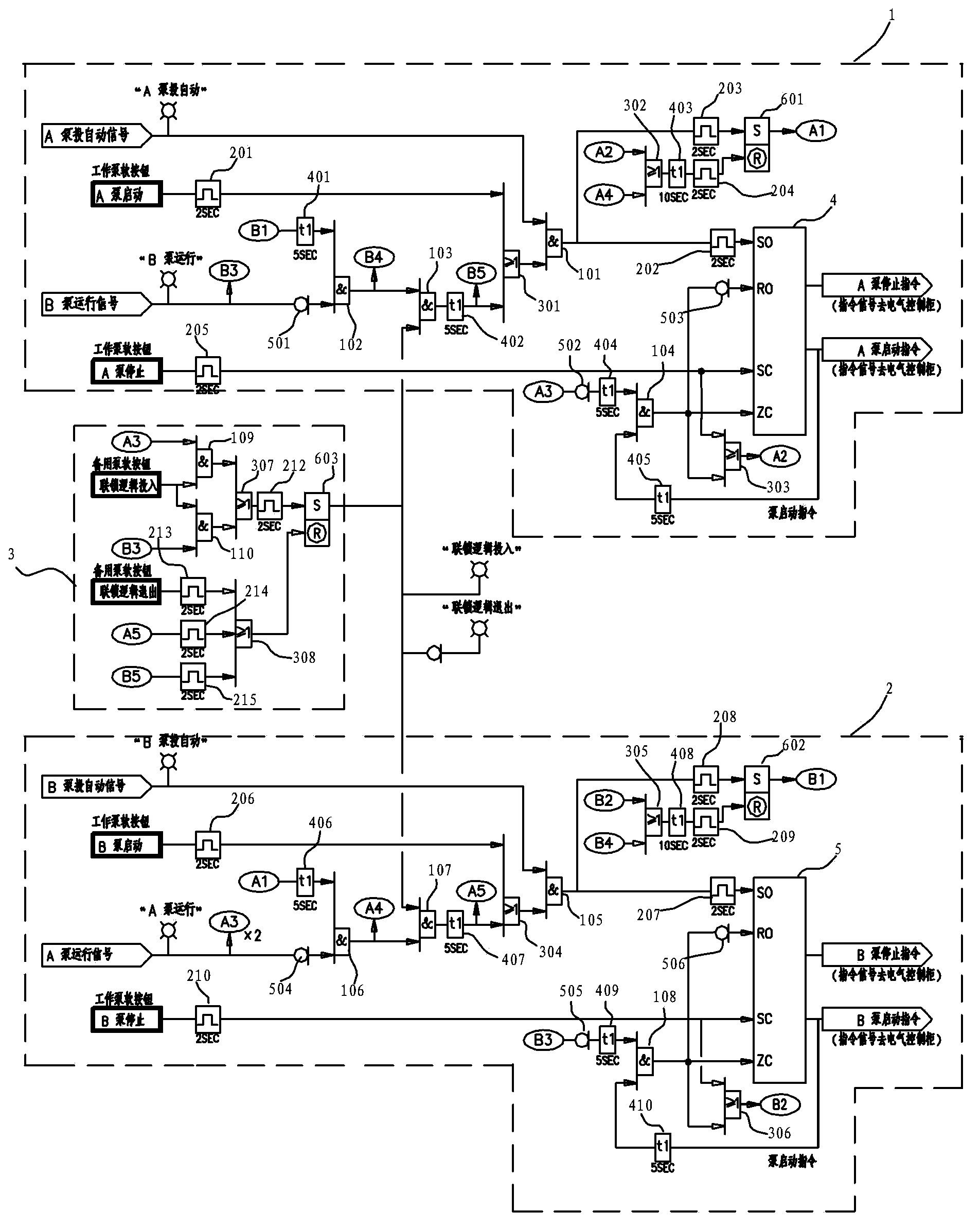
[0068] The present invention will be further described in detail below in conjunction with the accompanying drawings and embodiments.

[0069] The two pumps provided in this embodiment are mutually standby and the control logic of automatically starting the standby pump is set in the control system and connected with the electrical control cabinet for controlling the A pump and the B pump, and the electrical control cabinet is connected to the output There are dry contact signals for automatic switching of pump A, dry contact signals for automatic switching of pump B, dry contact signals for pump A running, and dry contact signals for pump B running. The above control logic includes pump A control logic 1 and pump B control logic 2 , Interlock logic control module 3 three modules, A pump control logic 1, B pump control logic 2 electrical control loop wiring mode is completely consistent, specifically:

[0070] A pump control logic 1 consists of:

[0071] The A pump automatic ...


PUM


Abstract

The invention relates to a stand-by pump automatically-starting control logic device with two pumps mutually serving as stand-by pumps. The stand-by pump automatically-starting control logic device is connected with an electrical control cabinet for controlling the A pump and the B pump. Dry contact signals for automatically starting the A pump, dry contact signals for automatically starting the B pump, dry contact signals for operating the A pump and dry contact signals for operating the B pump are output by the electrical control cabinet in a connecting mode. The stand-by pump automatically-starting control logic device is characterized by comprising an A pump control logic device body, a B pump control logic device body and an interlocking logic module. The electrical control return circuit of the A pump control logic device body and the electrical control return circuit of the B pump control logic device body are completely coincident in wiring. The interlocking logic module is additionally arranged. The interlocking logic module serves as a bridge to enable the two pumps to be ingeniously connected into a whole so that the operability of the two pumps can be easily achieved. The A pump and the B pump are controlled by the stand-by pump automatically-starting control logic device, therefore, the wrong motions of an operator can be reduced, the stand-by pump can be reliably and timely started, and the A pump and the B pump can completely and mutually serve as the stand-by pumps.

Description

technical field [0001] The invention relates to a control logic in which two pumps serve as backup for each other and automatically start the backup pump. Background technique [0002] At present, the control and monitoring of industrial production are basically completed by the control system (such as DCS distributed control system, PLC programmable logic controller, etc.). It is realized by the control system, and the design of the pump usually installs two pumps at one pump position, one for working and one for standby. The way of starting and stopping is: the operator starts the working pump, and when the working pump fails, the operator starts the standby pump or when the process parameters are abnormal, the instrument detects and sends the abnormal signal to the electrical control cabinet to start the standby pump. In this way, the electrical control circuit wiring for the working pump and the standby pump is different. [0003] In the existing technical solutions, t...

Claims


Application Information

Patent Timeline
IPC IPC(8): F04B49/06
Inventor 宋燕严春明顾颖
Owner SINOPEC NINGBO ENG
Why Eureka
Try Eureka