Reinforced synchronizer

A synchronizer and force-enhancing technology, applied in clutches, mechanical drive clutches, mechanical equipment, etc., can solve the problem of reducing the working reliability of the self-enhancing synchronizer, increasing the production cost of the self-enhancing synchronizer, and affecting the force increase. It can achieve significant economic and social benefits, reduce the volume of the drive device, and reduce the output force.

Inactive Publication Date: 2013-10-16
NANJING UNIV OF SCI & TECH
View PDF12 Cites 6 Cited by
  • Summary
  • Abstract
  • Description
  • Claims
  • Application Information

AI Technical Summary

Problems solved by technology

[0006] One is that the booster slopes on the two parts that produce the axial booster effect are separated from each other outside the synchronization stage. Before the booster slopes contact, one of the parts with the booster slope needs to complete the rotary motion and linear motion at the same time. At this time, it is difficult to ensure that the booster slopes on the two parts in the synchronization stage are in full contact, which obviously affects the booster effect of the self-energizing synchronizer;
[0007] The second is that after several shifts, there will be line contact between the opposite boosting slopes on the two parts, which not only affects the service life of the synchronizer, but also reduces the working reliability of the self-energizing synchronizer;
[0008] The third is that the two parts with the booster slope are processed separately, and a good booster effect cannot be obtained. Therefore, high requirements are placed on the machining accuracy of the force ramp angle, which not only increases the cost of the self-energizing synchronizer. The cost of production also affects the popularity of its promotion and application

Method used


Image

  • Reinforced synchronizer
  • Reinforced synchronizer
  • Reinforced synchronizer

Examples


Embodiment Construction

[0029] The present invention will be further described in detail below in conjunction with the accompanying drawings and specific embodiments.

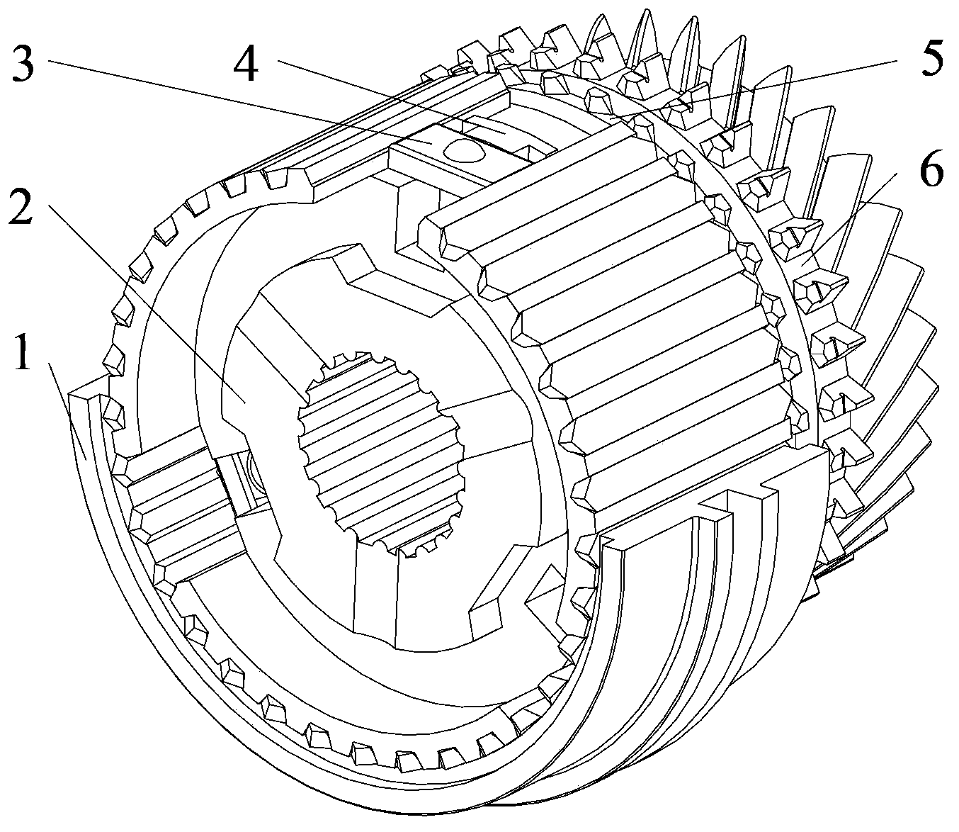
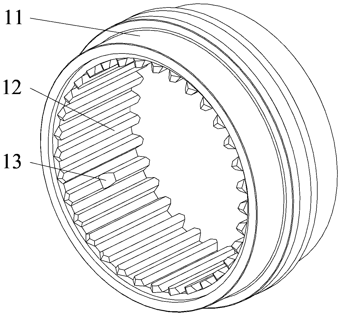
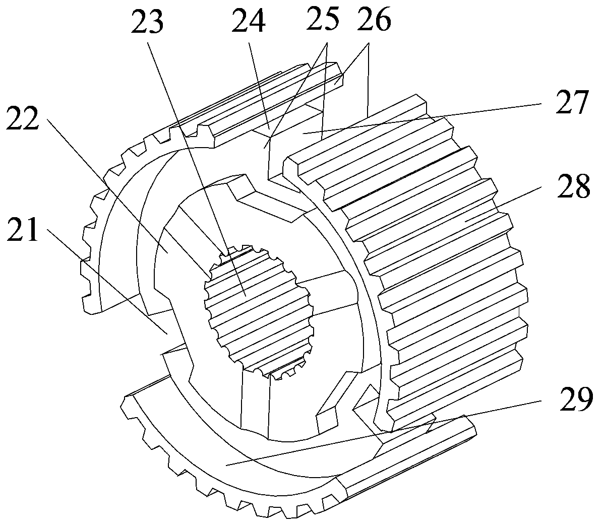
[0030] Such as Figures 1 to 12 As shown, the present invention proposes a booster synchronizer, which includes an adapter sleeve (1), a spline hub (2), a positioning slider (3), a synchronization ring (5) and a target gear (6), The adapter sleeve (1) is set on the spline hub (2), and a positioning slider (3) is provided between the adapter sleeve (1) and the spline hub (2); the spline hub (2) is provided with a concave The side of the groove (27) and the inner surface of the ring gear (29), the positioning slider (3) is provided with an axial end surface (32), and the target gear (6) is provided with an external friction cone (62), which is characterized in that the synchronization ring A booster ring (4) is provided between (5) and the splined hub (2), wherein:

[0031]The booster ring (4) is provided with a circular body (41), an...


PUM


Abstract

The invention relates to a reinforced synchronizer which comprises a joint sleeve, a spline hub, a positioning sliding block, a synchronizing ring and a target retaining gear. The reinforced synchronizer is characterized in that a reinforced ring is arranged between the synchronizing ring and the spline hub. An outer reinforced slant face is arranged on a reinforced bump at the outer end face of the synchronizing ring of the synchronizer. The reinforced synchronizer has the advantage of producing axial reinforcement in a synchronizing stage and amplifying output power of a drive device. When the reinforced synchronizer is applied to a manual speed changer, working intensity of a driver can be reduced and when the reinforced synchronizer is applied to the automatic speed changing technology, energy loss in a gear shifting process of a gear shifting actuator can be reduced. Meanwhile, the size of the gear shifting actuator can be further reduced, and a good technical base is provided for improvement of gear shifting quality. Compared with the prior art, the reinforcement efficacy is high and obvious economic benefits and social benefits can be produced.

Description

technical field [0001] The invention relates to an automobile gearbox, in particular to a booster synchronizer. Background technique [0002] The lock ring synchronizer uses the principle of friction to realize the speed synchronization of the input and output shafts of the transmission, and ensures that the splines in the sleeve and the ring gear of the target gear cannot contact before they are synchronized, thereby avoiding the impact and noise between the teeth and improving the shifting quality. In order to reduce the driver's work intensity when using a manual transmission or the energy loss of the driving device in the automatic transmission technology, the research on the synchronizer with self-energizing function has been paid more and more attention in the field of automobile transmission. [0003] In 1998, R.A. Nelums of Eaton Corporation of the United States invented a pin-type double-acting synchronizer with self-energizing function (patent application No. 98118...

Claims


Application Information

Patent Timeline
Patent Type & Authority Applications(China)
IPC IPC(8): F16D23/04
Inventor 李波常思勤林树森
Owner NANJING UNIV OF SCI & TECH
Why Eureka
Try Eureka