Numerical control driving device of crank-connecting rod-toggle rod plate shearing machine

A technology of crank connecting rod mechanism and driving device, applied in shearing device, shearing machine equipment, metal processing equipment and other directions, can solve the problems of low transmission efficiency, large width of guide rail, and oil leakage environment, etc., to improve the shearing width and precision, improve work efficiency, and the effect of high work efficiency

Active Publication Date: 2015-06-24
SUZHOU UNIV
View PDF6 Cites 0 Cited by
  • Summary
  • Abstract
  • Description
  • Claims
  • Application Information

AI Technical Summary

Problems solved by technology

Among them, the main technical problems of the hydraulic shearing machine are: 1. Oil leakage causes environmental pollution; 2. The transmission efficiency is low, resulting in a large waste of energy; 3. Hydraulic components such as pumps and valves are expensive and difficult to maintain ;4. The large hydraulic shearing machine requires a large flow rate of the hydraulic pump and a large volume of the fuel tank, resulting in a large system volume
The main technical problems of pneumatic shearing machine are: 1. The system pressure is low, so it can only be used in occasions with small shearing force; For occasions with large cutting width
The main technical problems of the traditional mechanical shearing machine are: 1. The level of automation control is low; 2. The guide rail must be used to guide the linear motion of the moving tool holder. For large shearing machines, the width of the guide rail will inevitably be too large and the structure will be complicated. Difficulty in manufacturing, increased manufacturing cost, and cannot guarantee cutting accuracy

Method used


Image

  • Numerical control driving device of crank-connecting rod-toggle rod plate shearing machine

Examples


Embodiment 1

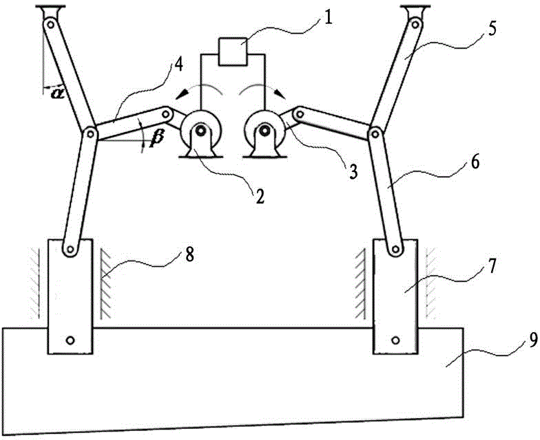
[0018] Embodiment one: see attached figure 1 shown.

[0019] Crank-connecting rod-knuckle rod shearing machine numerical control driving device, which includes a numerical control system 1, a motor 2, a transmission mechanism connected to the motor 2, a booster mechanism connected to the transmission mechanism, the first toggle lever 5, the second toggle lever 6, connected The slide block 7 of the booster mechanism, the slide block 7 is arranged in the chute 8, connects the moving tool rest 9 of the slide block, the transmission mechanism includes a crank linkage mechanism, and the booster mechanism includes the toggle mechanism, the first toggle lever 5, The second toggle 6, one end of the first toggle 5 is connected to the fuselage and the other end is connected to the second toggle 6, and the other end of the second toggle 6 is connected to the slider 7.

[0020] The crank-link mechanism includes a crank 3 and a connecting rod 4, one end of the crank is connected to the ro...


PUM


Abstract

The invention discloses a numerical control driving device of a crank-connecting rod-toggle rod plate shearing machine. The numerical control driving device of the crank-connecting rod-toggle rod plate shearing machine comprises a numerical control system, a motor, a transmission mechanism connected with the motor, a force increasing mechanism connected with the transmission mechanism, a sliding block connected with the force increasing mechanism and a movable knife rest. The numerical control driving device of the crank-connecting rod-toggle rod plate shearing machine is characterized in that the transmission mechanism comprises a crank connecting rod mechanism, the force increasing mechanism comprises a toggle rod mechanism, the sliding block is arranged in the sliding groove and fixedly arranged on the movable knife rest, one end of the toggle rod is connected with a machine body, and other end of the toggle rod is connected with the sliding block. A crank of the crank connecting rod mechanism is connected with a rotor of the motor, and a connecting rod of the crank connecting rod mechanism is connected with the middle of the toggle rod mechanism. The numerical control driving device of the crank-connecting rod-toggle rod plate shearing machine can improve shearing force and automatic control level of the mechanical plate shearing machine, simultaneously omits an oriented guide rail of the movable knife rest of the mechanical plate shearing machine, simplifies structure, and improves shearing width and accuracy of the plate shearing machine and working efficiency.

Description

technical field [0001] The invention relates to a numerically controlled driving device for a shearing machine, in particular to a numerically controlled driving device for a shearing machine whose driving mechanism is a crank-connecting rod-knuckle rod. Background technique [0002] Shearing machine is a shearing equipment for cutting and processing plates according to size requirements. It is the most widely used material cutting equipment in various industrial sectors. It is mainly used to cut straight edges of various sizes of metal plates and has a wide range of applications in the manufacturing field. CNC shearing machine refers to the technology of using digital instructions composed of numbers, characters and symbols to command the driving mechanism to realize the motion control of one shearing machine or multiple shearing machines. [0003] At present, the driving modes of the main movement of the shearing machine mainly include hydraulic, pneumatic and mechanical. ...

Claims


Application Information

Patent Timeline
Patent Type & Authority Patents(China)
IPC IPC(8): B23D15/12B23D15/06
Inventor 王传洋钟康民钟以波
Owner SUZHOU UNIV
Why Eureka
Try Eureka