Light source structure based on light conversion efficiency increment through fluorescent powder

A technology of light conversion and phosphor, which is applied to optical elements used to change the spectral characteristics of emitted light, light guides of lighting systems, optics, etc., and can solve the effects of phosphor excitation efficiency, unfavorable light output purity, and limited light conversion of light sources Efficiency and other issues, to achieve the effect of improving light conversion efficiency, meeting the requirements of light purity, and low cost

Active Publication Date: 2013-10-16
APPOTRONICS CORP LTD
View PDF4 Cites 3 Cited by
  • Summary
  • Abstract
  • Description
  • Claims
  • Application Information

AI Technical Summary

Problems solved by technology

Its disadvantage is that the greater the heat generated by the light-emitting chip, the greater the impact on the excitation efficiency of the phosphor
Its shortcoming is that as the light source technology continues to develop, the output brightness and power of the light source are getting higher and higher. This structure ignores the influence of the heat energy accumulated by the phosphor itself on the light conversion efficiency under high excitation light power, which limits the light source. Further improvement in light conversion efficiency
[0008] The disadvantage of the above-mentioned prior art is that although the scheme disclosed in U.S. Patent No. 7,196,354B1 can maximize the efficiency of the light source, in the structure of the light source disclosed in the patent, the light emitted by the fluorescent powder is not absorbed and utilized. The excitation light can be passed through direct (eg figure 1 a) or reflection (as in figure 1 As shown in b) is emitted from the exit surface of the light source, which is not conducive to improving the purity of light output

Method used


Image

  • Light source structure based on light conversion efficiency increment through fluorescent powder
  • Light source structure based on light conversion efficiency increment through fluorescent powder
  • Light source structure based on light conversion efficiency increment through fluorescent powder

Examples


Embodiment Construction

[0030] Below, the present invention is further described in conjunction with the preferred embodiments shown in the accompanying drawings.

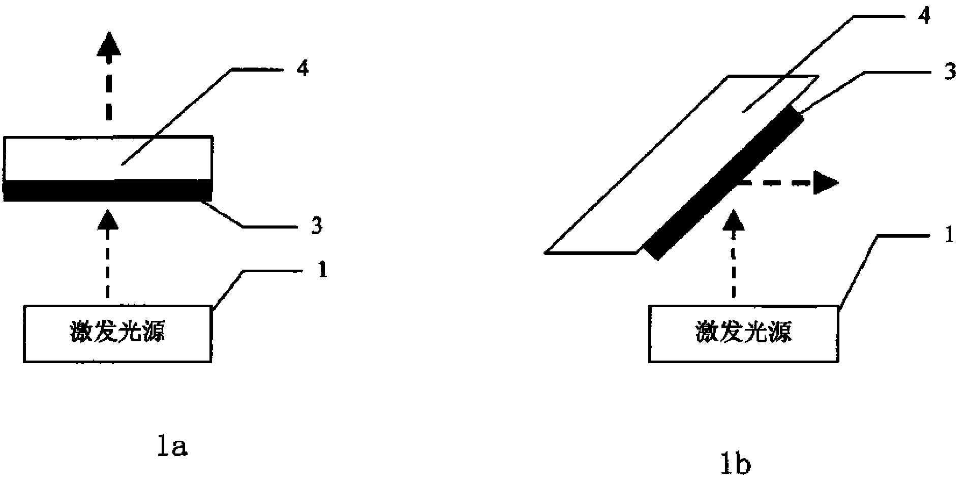
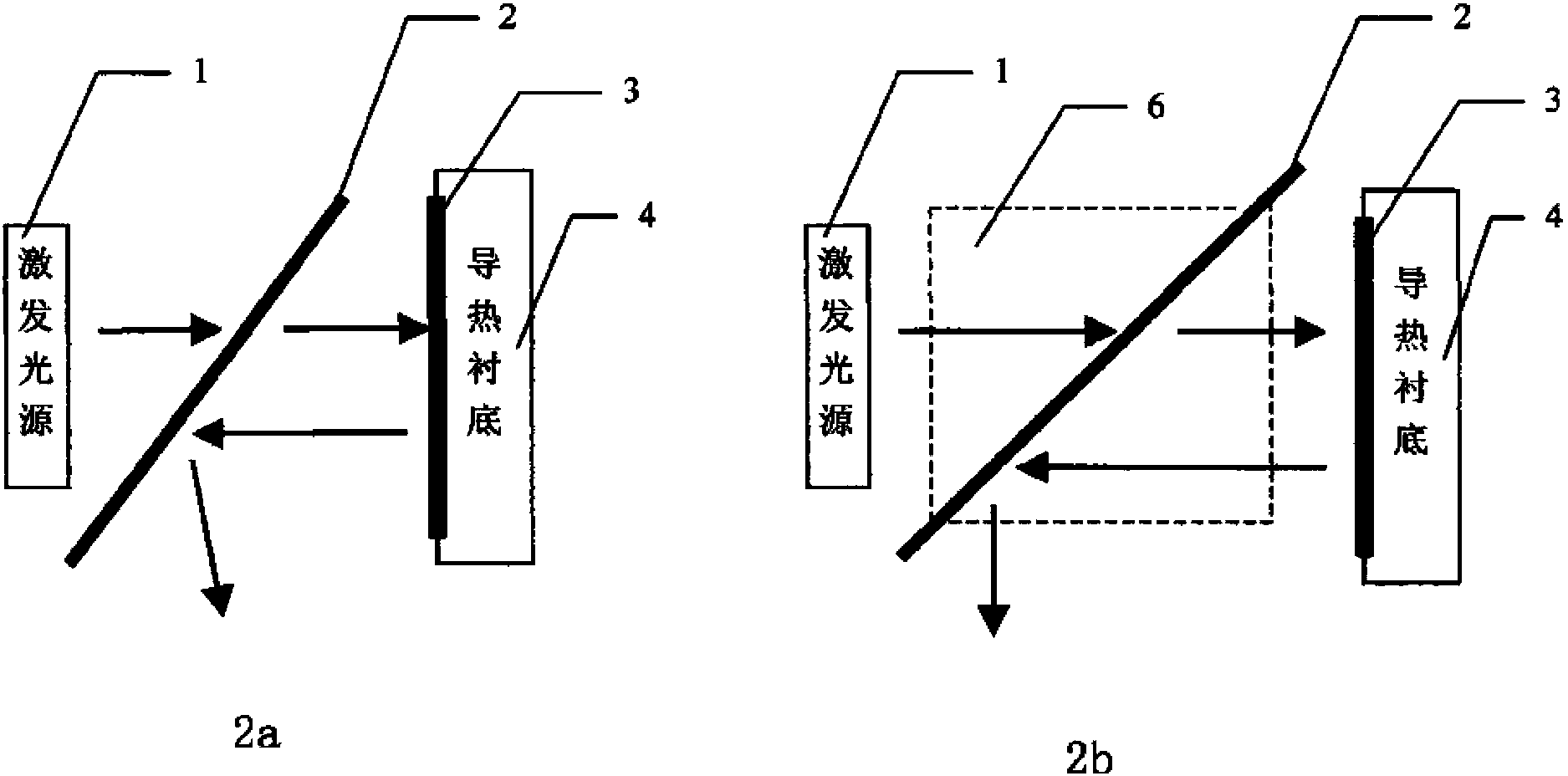
[0031] The light source of the present invention includes at least an exciting light source 1, an excited material 3, and a thermally conductive substrate 4; the excited material 3 is closely attached to the thermally conductive substrate 4, so that the accumulated heat is conducted and diffused in time. In order to make the light output directional conduction and have higher purity, the light source of the present invention also includes a spectroscopic filter 2, so that the excitation light source 1 faces the spectroscopic filter 2, so that the excitation light obliquely shoots to the spectroscopic filter 2 , and at the same time, the excited material 3 is arranged to be roughly facing the excitation light guided by the spectral filter 2 (that is to say, the plane formed by the excited material 3 is approximately perpendicular to the chi...


PUM


Abstract

A light source structure based on light conversion efficiency increment through fluorescent powder comprises an excitation light source (1), an excited material (3) and a heat conduction substrate (4), as well as a spectral filter (2), wherein the excited material (3) is in joint with the heat conduction substrate (4); the excitation light source (1) faces the spectral filter (2) to cause the exciting light to emit obliquely to the spectral filter (2); the excited material (3) bears down on the exciting light directed from the spectral filter (2) straight; arranging a heat conduction mirror between the excited material (3) and the heat conduction substrate (4) can increase the use ratio of the excited luminescence. Through adopting the light source structure, the light source efficiency is improved and the advantages of simple realization structure and low cost are achieved.

Description

[0001] This application is a divisional application of the divisional application 201110142850.1 with the application number 200810065225.X submitted by the applicant on January 29, 2008. technical field [0002] The present invention relates to a light source module, in particular to a light source module based on fluorescent powder excitation, especially to an improved structure of a light source that makes outgoing light purer by means of element combination. Background technique [0003] Since the early 1990s, with the rapid development of a new generation of semiconductor optoelectronic materials based on InGaAlP and InGaN, various high-power and high-brightness red, yellow, blue, green, ultraviolet and white LED light sources have emerged. , emerge in endlessly, and have been more and more widely used in various display and lighting fields. [0004] In addition to using light-emitting diodes of corresponding colors, the main technical solutions that can be used to obta...

Claims


Application Information

Patent Timeline
Patent Type & Authority Applications(China)
IPC IPC(8): F21V9/10F21V7/22F21V8/00F21V9/40
Inventor 李屹杨毅
Owner APPOTRONICS CORP LTD
Why Eureka
Try Eureka