Laser strapdown inertial navigation system
A strapdown inertial navigation and laser technology, applied in the field of inertial navigation, can solve the problems of poor versatility and high cost, and achieve the effect of strong versatility and cost reduction.
Inactive Publication Date: 2013-10-16
NORTHWESTERN POLYTECHNICAL UNIV
3 Cites 15 Cited by
AI-Extracted Technical Summary
Problems solved by technology
[0010] The purpose of the present invention is to overcome the defects of high cost and poor versatility in the prior art, and provide a simple, effecti...
View moreMethod used
For improving frequency stabilization precision, as shown in Figure 15, the light signal that gyroscope model output is converted into electric signal by photoelectric signal conversion device, then enters D/A converter by analog switch; The digital signal of output passes through test circuit Control the A/D conversion, output the cavity length feedback control signal; the analog signal is amplified by the high-voltage circuit, and drive the piezoelectric ceramic model on the laser gyro reflector, and control the expansion and contraction of the reflector through the charging and discharging effect of the...
View moreAbstract
The invention discloses a laser strapdown inertial navigation system comprising a human-machine interaction interface module, a dynamic trajectory generation, a sensor module, a software error model, sensor simulation excitation hardware module, and a laser inertial navigation computer electronic component. With the system provided by the invention, cost is effectively reduced, and excessive consumption caused by the purchasing of physical inertial sensors or an actual flight test or a flight simulation test during testing, adjusting, and performance evaluation of the strapdown inertial navigation system computer electronic component are avoided. The system has high versatility, and can simulate inertial sensors of various types, such that the performance of a strapdown inertial navigation system computer electronic component can be comprehensively verified.
Application Domain
Technology Topic
Image
Examples
- Experimental program(1)
Example Embodiment
[0050] The present invention will be further described in detail below with reference to the drawings and specific embodiments.
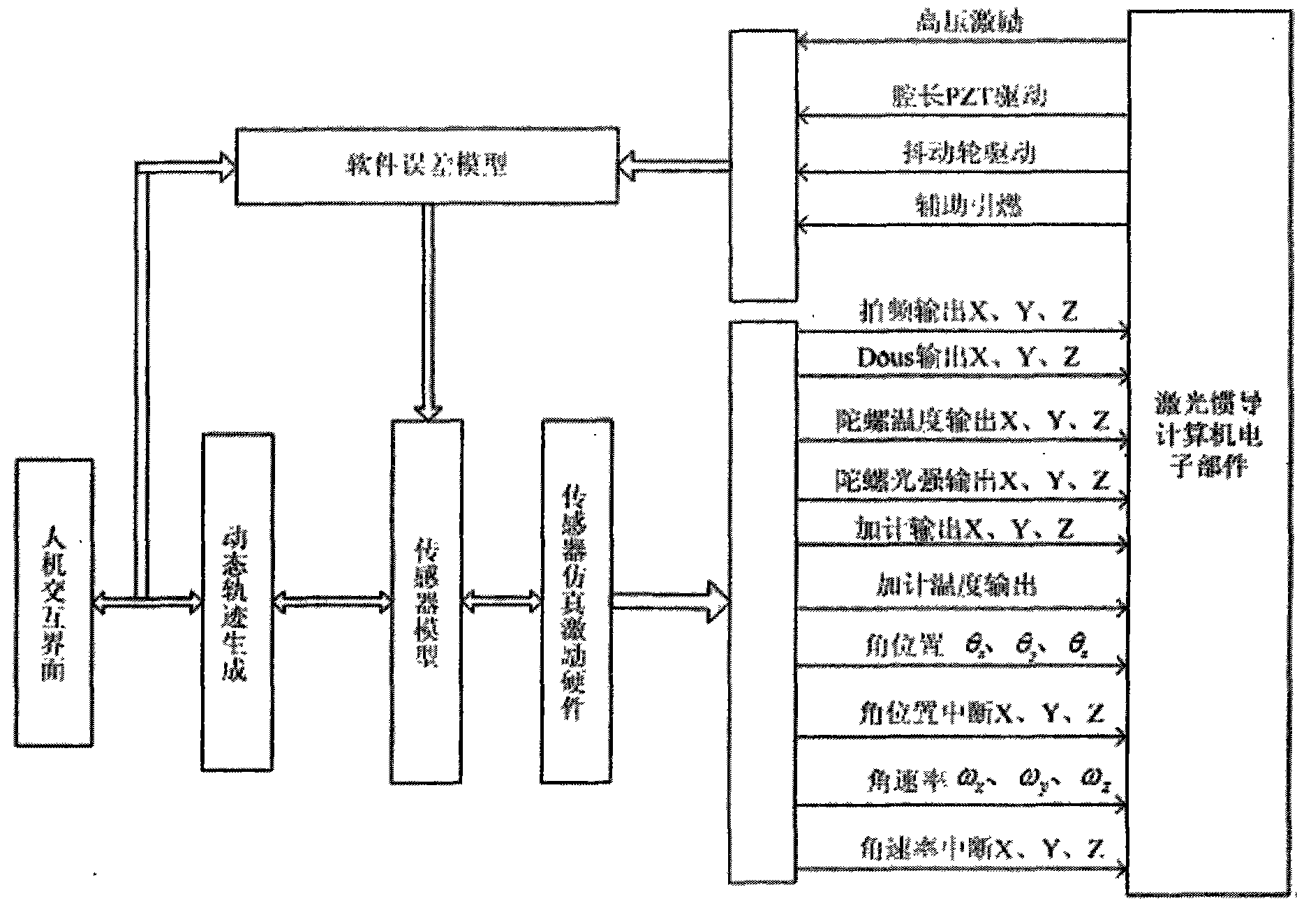
[0051] Such as figure 1 As shown, a laser strapdown inertial navigation system is characterized in that the system includes:
[0052] Man-machine interface module: used to realize man-machine dialogue, parameter setting of carrier motion trajectory in simulation system, software gyroscope and accelerometer model parameter setting and simulation result display;
[0053] Dynamic trajectory generation: used to generate aircraft trajectory;
[0054] Sensor module: The attitude angle information and accelerometer information at a certain time point output by the dynamic trajectory generation algorithm module are used as the input of the software sensor, and the attitude of the aircraft at that time is calculated by the mathematical model of the gyroscope and the accelerometer model Information and acceleration information;
[0055] Software error model: used to establish the gyroscope error model and acceleration error model, and respectively compensate the software gyroscope and software accelerometer;
[0056] Laser inertial sub-components;
[0057] Sensor simulation excitation hardware: It is the hardware interface that realizes the connection with the laser inertial conduction sub-component, which can generate beat frequency output, Dous signal output, gyro light intensity output, accelerometer output, angular position output, angular rate output signal; receiving cavity length PZT Drive, jitter wheel drive signal; provide interface with laser sensor simulation software module.
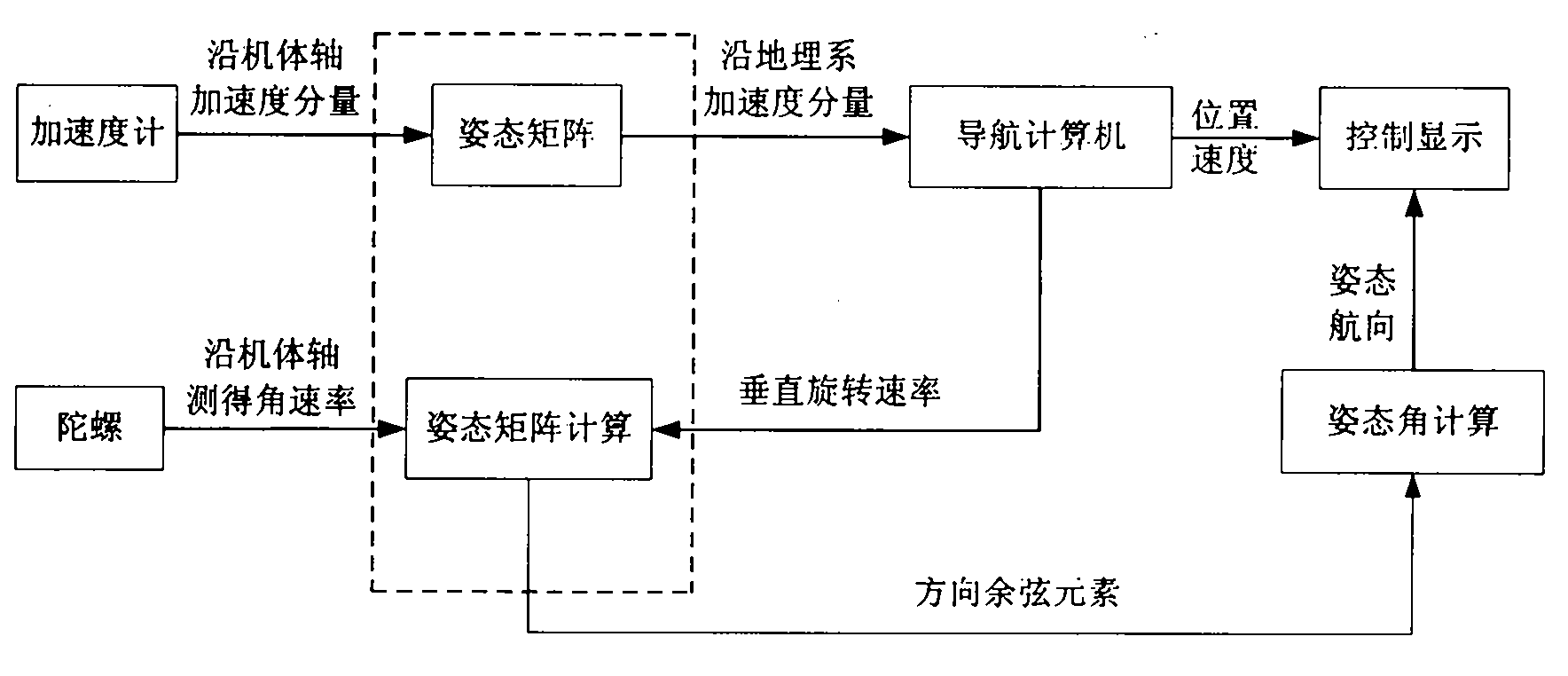
[0058] Such as figure 2 As shown, the three-axis gyroscope and accelerometer are respectively sensitive to the angular motion information and linear motion information of the axis, and these information are collected and processed, input into the navigation computer, and the carrier's motion information is obtained through calculation. And correct the state of carrier movement.
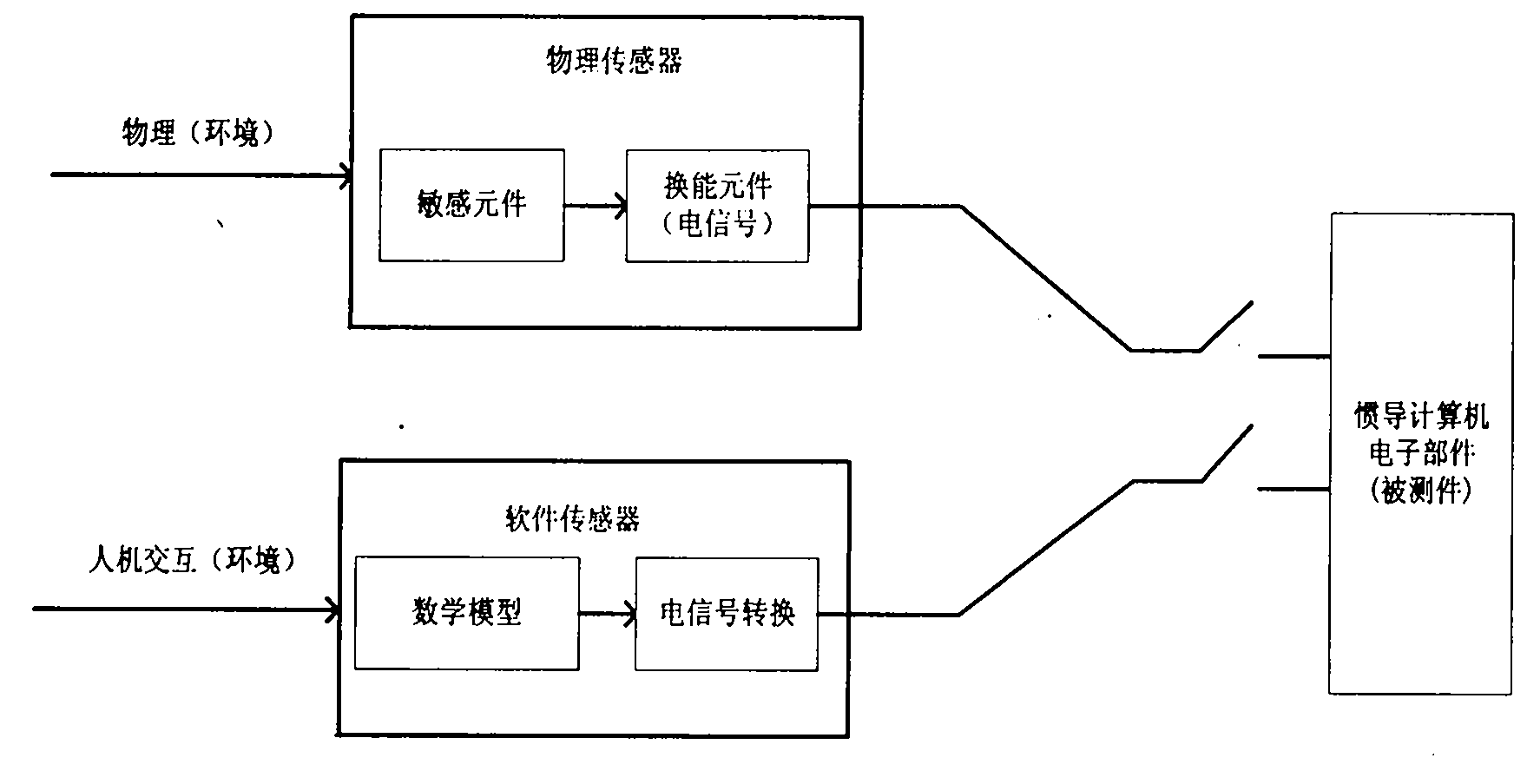
[0059] figure 2 In the strapdown inertial navigation hardware-in-the-loop simulation test system shown, in order to simulate figure 1 The electrical signal in the MV is set through human-computer interaction (or automatically generated by the program) to set the carrier motion state, and decompose the carrier motion state to obtain carrier motion information (mainly attitude information and acceleration information); the navigation coordinate system uses the Northeast Sky geographic coordinate system, Transform the attitude matrix to the northeast sky geographic coordinate system, and use the attitude information and acceleration information of the carrier as the known parameters of the mathematical model to solve the mathematical model. The result of the solution can be obtained by simulation after a conversion circuit. image 3 The electrical signal in is used to verify the reliability of the DUT.
[0060] The working principle of each module of the system of the present invention:
[0061] (1) Human-computer interaction interface module
[0062] The human-computer interaction interface module is used to realize the functions of man-machine dialogue, the parameter setting of the carrier motion trajectory in the simulation system, the parameter setting of the gyroscope model and the accelerometer model, and the display of simulation results.
[0063] A combination of Matlab simulation model, LabView development environment and C language is used to realize the human-computer interaction interface module.
[0064] Since the laser strap-down inertial navigation sensor hardware-in-the-loop dynamic simulation test system is a real-time hardware-in-the-loop simulation system, it is difficult to meet the requirements by using a software simulation alone. The specific implementation is as follows: According to the mathematical model of the software sensor, the Matlab model of the software sensor is constructed, and then the relevant functions of Matlab are used to convert the model into C code, and then the C code generated above is called by LabView, and debugging is carried out in the LabView environment.
[0065] (2) Dynamic trajectory generation module
[0066] The dynamic trajectory generation algorithm module is used to generate aircraft trajectories. In order to simulate the output information of the gyroscope and accelerometer, the trajectory of the aircraft is simulated by the method of computational simulation. Generate inertial device information sources (acceleration and angular velocity) according to the simulated track, and give the navigation parameters (attitude, speed and position) of the corresponding track point.
[0067] First, set the flight process of the airplane through the human-computer interaction panel. The flight state of the airplane is relative to the earth's surface (local geographic coordinate system). The basic motion state can be changed by the change of the airplane attitude angle (ω(t)) And aircraft acceleration (a t (t)) is given. The flight movement status is as follows:
[0068] ①Stationary or uniform linear motion: When the aircraft is stationary or in a uniform linear motion, the rate of change of the attitude angle (pitch angle θ, roll angle γ and heading angle ψ) is zero, and the acceleration of the aircraft is also zero, namely ω 1 (t)=[θ 0 γ 0 ψ 0 ] T , A t (t)=[0 0 0] T;
[0069] ②Acceleration (or deceleration): Assuming that the attitude angle of the aircraft does not change when accelerating (or decelerating), there is acceleration a, namely ω, along the direction of flight path 1 (t)=[θ 0 γ 0 ψ 0 ] T , A t (t)=[0 a 0] T;
[0070] ③Turning: The turning movement of the aircraft can be divided into three stages, namely, changing the roll angle to enter the turning stage, maintaining the roll angle to turn at a constant angular rate, and the roll angle leveling stage after turning.
[0071] Suppose the speed when turning is v and the angular rate is ω 2 (t)=[θ 0 γ 2 ψ 2 ] T , When entering the turning phase, the roll angle is at a constant angular velocity γ 2 Change without the acceleration, then
[0072] Entering the turning phase ω(t)=[0 γ 2 0] T , A t (t)=0
[0073] Turning phase ω(t)=[0 0 ψ 2 ] T , A t (t)=[ψ 2 v 0 0] T
[0074] The analysis of the leveling phase is the same as that of the turning phase.
[0075] ④ Ascend (or descend): Suppose that the speed of the carrier along the trajectory is kept constant during the whole process. The climb process is analyzed in three phases, namely the pull-up phase to change the pitch angle, the equal-angle climb phase and the leveling phase at the end of the climb.
[0076] In the pulling-up phase, the carrier makes a circular motion on the vertical plane, and the radius is R, and the carrier pitch angle is at a constant angular rate θ 3 Gradually increase to the angle when climbing Time t 1 , Then
[0077]
[0078] ω(t)=[θ 3 0 0] T
[0079] a t (t)=[0 0 θ 3 2 R] T
[0080] The attitude angle, heading angle and acceleration of the carrier are unchanged during the climb phase
[0081] The analysis of the leveling phase is the same as the pulling up phase.
[0082] Set the flight parameters of the aircraft (attitude angle: pitch angle θ, roll angle γ and heading angle ψ; acceleration: a x , A v , A z; Speed v x , V y , V z And position: λ, L, h), assign different values to the flight parameters, you can get the dynamic trajectory, you can simulate the take-off base as the origin, from take-off, climb, cruise, maneuver flight, descent and landing. Complete flight trajectory composed of flight phases.
[0083] (3) Sensor model module
[0084] The sensor model module takes the attitude angle information and accelerometer information at a certain time point output by the dynamic trajectory generation algorithm module as the input of the software sensor, and calculates the attitude of the aircraft at that time by the mathematical model of the gyroscope and the accelerometer model. Information and acceleration information.
[0085] The sensor module includes:
[0086] (I) Software sensor: The software sensor includes two parts: mathematical model and conversion circuit. The posture information and acceleration information are respectively used as the known parameters of the gyroscope and accelerometer models, and the mathematical model is solved, and the result is obtained through a conversion circuit to obtain electrical signals that characterize the carrier’s posture and acceleration. Mathematical models include laser gyroscope mathematical model and accelerometer model;
[0087] (II) Software sensor output, such as Figure 5 Shown
[0088] (III) Software sensor measurement: The software sensor measurement is to use the aircraft's attitude angle information and acceleration information at the current time on the ideal trajectory as the input of the software gyroscope and accelerometer respectively, plus the attitude angle increment and acceleration increase within the time period. After injecting gyro noise and accelerometer noise to calculate, simulate the output process of the actual inertial measurement element at the moment.
[0089] The angular velocity increment and acceleration increment can be solved by the corresponding angular increment differential equation and acceleration increment differential equation.
[0090] The output of gyroscope and accelerometer can be obtained through two processes of ideal trajectory simulation and software sensor measurement.
[0091] (IV) Inertial device measurement increment information
[0092] Angular increment
[0093] Δ φ · = ω ib b = C n b ( ω in n + C b n ω nb b ) = C n b ω in n + ω nb b
[0094] among them
[0095] ω nb b = C γ C θ 0 0 - ψ · + C γ θ · 0 0 + 0 γ · 0 = cos γ 0 sin γ cos θ 0 1 - sin θ sin γ 0 - cos γ cos θ ω in n = ω ie n + ω en n ω ie n = 0 , ω ie cos L , ω ie sin L T ω en n = - v N n / ( R M + h ) , v E n / ( R N + h ) , v E n tan L / ( R N + h ) T
[0096] Acceleration increment
[0097] Δ v · = f sf b = C n b f sf n
[0098] among them
[0099] f sf n = v · n + ( ( ω en n + 2 ω ie n ) X ) v n - g n
[0100] In summary, let x(t)=[θ γ ψ v n L λ h Δφ Δv] T , The trajectory differential equation can be obtained as follows:
[0101] x · ( t ) = f [ x ( t ) , ω ( t ) , a t ( t ) , t ]
[0102] To change the partial equations, the fourth-order Runge-Kutta numerical method can be used to obtain the solution of each partial equation.
[0103] (4) Software error module
[0104] In order to simulate the laser gyroscope and accelerometer more accurately and improve the accuracy of the software sensor, the gyroscope error model and acceleration error model are established, and the software gyroscope and software accelerometer are respectively compensated for errors. The principle of compensation error is as Image 6 Shown.
[0105] In the figure, ω and A respectively represent the angular velocity and acceleration of the carrier relative to the inertial space movement; with Respectively represent the original solution value output by the mathematical model of the gyroscope and the accelerometer model; δ ω And δ A Respectively represent the estimated value of the solution error of the gyroscope and accelerometer calculated by the error model; with Respectively represent the angular velocity after error compensation and the calculated value of the accelerometer.
[0106] Such as Figure 7 As shown, the mathematical model and the gyroscope and accelerometer in engineering applications have certain errors. In order to make the output result of the simulation better approximate the real gyroscope and accelerometer, error correction is added to the output of the software sensor, and the test characteristic curve of the real gyroscope and accelerometer is simulated by machine learning.
[0107] (5) Laser inertial conduction sub-component module
[0108] (6) Sensor simulation excitation hardware module
[0109] The sensor simulation excitation hardware module is a hardware interface that realizes the connection with the laser inertial conduction sub-component, which can generate beat frequency output, Dous signal output, gyro light intensity output, accelerometer output, angular position output, angular rate output signal; receiving cavity length PZT Drive, jitter wheel drive signal; provide interface function with laser sensor simulation software module.
[0110] 1. Realization of the software model of the jittered laser gyroscope
[0111] The software gyroscope structure is as Figure 8 As shown, the software gyro is composed of three parts: gyro model, jitter control and cavity length control.
[0112] The following is a detailed analysis of the realization of jitter control and cavity length control loop.
[0113] (1) Principle of jitter control and cavity length control
[0114] (I) Jitter control
[0115] The jitter bias requires that the frequency and amplitude of the sinusoidal mechanical jitter remain stable. In order to ensure that the amount of jitter deviation is appropriate, the jitter sensitivity must be the maximum value, that is, the jitter frequency must be equal to the resonant frequency of the jitter mechanism, and the circuit must be able to automatically track and stabilize at this frequency.
[0116] If the resonant frequency and maximum jitter sensitivity of the jitter mechanism cannot be maintained at a constant value, the jitter amplitude will change as a result. The jitter control circuit must be compensated through closed-loop feedback to keep the jitter amplitude stable. In addition to amplitude control, a complete jitter control circuit must also have the ability to make the jitter frequency track the resonant frequency of the jitter mechanism.
[0117] (II) Cavity length control
[0118] The function of the ring cavity of the laser gyroscope is to feed the light amplified by the gain medium into the gain medium again for re-amplification. But the light fed back must match the original light in phase to form a stable oscillation, that is, when the light wave from any point circles the ring cavity and returns to its original position, the phase change is equal to an integer multiple of 2π. The conditions for forming oscillation are
[0119] nL λ q 2 π = q 2 π
[0120] In the formula, L is the length of the laser cavity; n is the refractive index of the medium in the cavity; q is a positive integer, and each q corresponds to a longitudinal mode, λ q Is the laser wavelength.
[0121] Laser resonance frequency uses v q =c/λ q , Where c is the speed of light, then
[0122] v q = qc nL
[0123] The stability of the laser resonance frequency is mainly determined by the cavity length L and the change of the refractive index n of the medium in the cavity. The refractive index of the gyro remains basically unchanged during the working process, so the gyro frequency stabilization generally only needs to keep the cavity length L from the influence of the environment and the internal factors of the resonant cavity, and the purpose of frequency stabilization can be achieved. Therefore, the gyro frequency stabilization is also called cavity length control. .
[0124] The frequency stabilization of the laser gyroscope uses piezoelectric ceramics (Piezoelectric, PZT) to drive one or multiple mirrors of the ring cavity to translate in the direction of the mirror normal to realize the adjustment of the laser cavity length and set the longitudinal mode frequency to v q Place. The maximum light intensity represents a certain fixed light frequency determined by the gain medium. When the cavity length changes, the resonance frequency changes, which leads to the change of light intensity. By detecting light intensity and feedback control, the laser frequency can be stabilized at the maximum light intensity.
[0125] (2) Software model
[0126] The "half-physical dynamic simulation system" of the dithered laser gyroscope to be realized should have the following Picture 9 The architecture shown:
[0127] Picture 10 The detailed structure diagram of the semi-physical simulation system is as follows.
[0128] Among them, DSP plans to use TI's TMS320C31, which is a relatively high cost-effective floating-point processor. Has the following characteristics:
[0129] Abundant hardware resources: It contains a 2K*32-bit fast RAM block; separate program bus, data bus and DMA bus make it possible to fetch instructions, read and write data and DMA operations in parallel; use 64*32-bit instruction Cache To store frequently used code blocks, which can greatly reduce the number of off-chip accesses, thereby increasing the speed of the program; up to 16M 32-bit words of memory space can be accessed.
[0130] TMS320C31 peripherals control the peripheral bus through memory-mapped registers, allowing direct communication with peripherals.
[0131] In addition, TMS320C31 also has the advantages of rich instruction system, flexible program control, pipeline operation and various addressing modes.
[0132] (I) Jitter model
[0133] The jitter model must be established on the basis of the real device, so that it can seamlessly connect with the actual control circuit. The reference hardware circuit such as Picture 11 Shown.
[0134] The mathematical model of jitter can be equivalent to a sine function (simple pendulum) (in actual implementation, it can also be equivalent to a piezoelectric equation, so the implementation may be more realistic), and the parameter is the angular frequency.
[0135] (II) Cavity length model
[0136] Since we know that the cavity of the laser gyroscope is quartz, and quartz is a piezoelectric material, we will use the backpressure effect to build the cavity length model. The specific method is to build the model through the piezoelectric equation and the characteristics of the material.
[0137] Commonly used mathematical modeling methods include mechanism modeling method and identification modeling method. Mechanism modeling method (also known as deductive method) is based on the physical process mechanism of actual system work. Under certain assumptions, in accordance with the corresponding physical theory, Write out the equation representing its physical process, combine the boundary conditions and initial conditions, and then use appropriate mathematical processing methods to obtain a mathematical model that can correctly reflect the dynamic and static characteristics of the actual object; the identification modeling method (also called the induction method) is to use System identification technology uses various identification algorithms to establish a dynamic and static mathematical model of the system based on the input and output data obtained during the operation of the system model or the experiment. This project intends to adopt the mechanism modeling method to analyze and obtain the differential equations or differential equations describing the laser gyro, and then use the computer to solve and analyze the mechanism and phenomenon of the laser gyro.
[0138] The fourth type of piezoelectric equation is used to establish the cavity length model. The boundary conditions of the fourth type of piezoelectric equation are mechanical clamping and electrical open circuit. Strain S and electrical displacement D are independent variables, and stress T and electric field strength E are dependent variables:
[0139] h-type T = c D S - h t D E = - hS + β S D
[0140] Where h-piezoelectric stress constant; h t -h transpose, β S Is the dielectric isolation rate under constant strain (clamping); c D It is the elastic stiffness coefficient at constant electric displacement (open circuit).
[0141] (3) Realization scheme of jitter control and cavity length control
[0142] The realization principle of jitter control and cavity length control is as follows Picture 12 Shown.
[0143] Jitter control loop: The signal acquisition module collects the jitter control quantity from the DUT to obtain the jitter control signal (electric signal); the signal is converted into a signal representing the jitter control increment, and the incremental signal is used as the input of the jitter mathematical model; jitter mathematics The model represents the motion characteristics of the jitter wheel (such as B d =Asinωt).
[0144] Cavity length control loop: The signal acquisition module collects the cavity length control value from the test piece, obtains the cavity length control signal (electric signal), and converts it into a signal that characterizes the amount of electricity and the expansion and contraction of the piezoelectric ceramic, which is used as the input of the expansion control model; The expansion control model reflects the proportional relationship between voltage and piezoelectric material expansion (such as V L =Kl).
[0145] The output of the jitter mathematical model, the attitude information in the ideal track, the noise and the output of the telescopic control model are used as the input of the software gyroscope, and the output information of the gyroscope is obtained by solving, and the information is fed back to the DUT to form a complete The jitter control loop and cavity length control loop.
[0146] (I) Realization of jitter control
[0147] Such as Figure 13 As shown, the output of the mechanical jitter offset laser gyro contains the inertial angular velocity information (the angular velocity to be measured) and the angular velocity information of the jitter signal. In other words, the input angular velocity of the laser gyro Ω includes the angular velocity to be measured Ω r And the angular velocity introduced by the offset frequency Ω B.
[0148] The frequency f=Δv of the electrical signal output by the laser gyro includes the angular velocity Ω to be measured r And offset angular velocity Ω B Frequency difference caused by Δv r And Δv B , And the zero drift Δv caused by the gas flow caused by the temperature gradient D. Zero drift Δv D It is an inherent error of the laser gyro itself, which can be dealt with by establishing an error model. Δv caused by jitter offset B Need to use the demodulation method to change the offset angular velocity Ω B The resulting frequency difference Δv B Eliminate, so as to be able to get the magnitude and direction of the angular velocity to be measured.
[0149] In the jitter control model, the jitter bias requires that the frequency and amplitude of the sinusoidal mechanical jitter remain stable, that is, the jitter frequency must be equal to the resonant frequency of the jitter mechanism. Specific control loop such as Figure 14 Shown.
[0150] In the figure, the A/D signal acquisition module collects the signal from the DUT to obtain the jitter control signal, which is decomposed into two parts: the amplitude control signal and the frequency control signal; the amplitude control signal is used as the amplitude control parameter, and the frequency control signal is used as the frequency Control parameters; amplitude control maintains the amplitude of the jitter model stable at the level given by the jitter amplitude control signal, and frequency control maintains the frequency of the jitter model stable at the jitter resonance frequency.
[0151] The jitter does not eliminate the lock area, but only "slices" the large lock area into a series of small lock areas located near integer multiples of the jitter frequency, and injects random noise into the frequency control to eliminate the small lock area error.
[0152] The amplitude control loop realizes amplitude demodulation, and the frequency control loop realizes phase demodulation. The amplitude control and frequency control are respectively realized by establishing corresponding mathematical models.
[0153] Taking a single free pendulum as the jitter model, the motion equation of the single free pendulum is
[0154] θ · · + 2 β θ · + sin θ = f cos Ωt
[0155] In the formula, β is the damping coefficient and f is the driving force.
[0156] (II) Realization of cavity length control
[0157] Frequency stabilization is an important indicator that determines the performance of the gyro. Generally, the length of the gyro cavity is adjusted by detecting the light intensity output by the laser gyro to achieve the purpose of controlling the relative frequency stability. The magnitude of the light intensity modulation amplitude indicates the degree of difference between the laser frequency and the center frequency, and the phase relative to the added modulation indicates which side of the center frequency the laser frequency is located. The piezoelectric ceramic model has an inverse piezoelectric effect, and when a voltage is applied across it, it will deform slightly along the polarization direction.
[0158] In the actual frequency stabilization design, there are two frequency stabilization methods, namely DC frequency stabilization and AC frequency stabilization. The main difference between them lies in the source of the light intensity error signal: for DC frequency stabilization, the light intensity error signal is taken from The DC signal output by the photoelectric conversion device; and the AC frequency-stabilized light intensity error signal is the AC amplitude signal output by the preamplification of the AC part output by the photoelectric conversion device, and then the detection output. Regardless of the frequency stabilization method, the error signal is differentially amplified, and then accumulated by the integrator to achieve error-free frequency stabilization. The integrated signal is then amplified and output by the drive circuit to drive the piezoelectric ceramic to change the cavity length.
[0159] To improve the frequency stabilization accuracy, such as Figure 15 As shown, the optical signal output by the gyro model is converted into an electrical signal through the photoelectric signal conversion device, and then enters the D/A converter through the analog switch; the output digital signal is controlled by the test circuit to control the A/D conversion, and the cavity length feedback control signal is output ; The analog signal is amplified by the high-voltage circuit to drive the piezoelectric ceramic model on the laser gyro reflector. The charge and discharge effect of the piezoelectric ceramic is used to control the expansion and contraction of the reflector, adjust the control voltage for positive or negative changes, and then adjust the gyro The cavity length achieves the purpose of stabilizing the laser frequency. Among them, the piezoelectric ceramic model uses the model control algorithm to control its length to realize the control of the resonant optical path length.
[0160] Piezoelectric ceramics work in the linear region, and the change of the cavity length controlled by it is proportional to the change of the applied voltage; the change of resonant frequency is proportional to the change of the cavity length controlled by the piezoelectric ceramic; at the stable frequency operating point In the vicinity, the change of left and right rotation light intensity is approximately proportional to the change of resonance frequency, and the proportional coefficients are equal in size and opposite in direction.
[0161] (4) Mathematical description of jittered laser gyro model
[0162] a) Basic mathematical model of laser gyroscope
[0163] Δf=KΩ r
[0164] Where Δf is the frequency difference, K is the scale factor, Ω r Is the angular velocity to be measured; that is, the frequency difference between the two beams of light is proportional to the input angular velocity.
[0165] The frequency of the electrical signal output by the laser gyro includes only the angular velocity to be measured Ω r Frequency difference caused by Δv r ,which is
[0166] Δf 1 =KΩ r =Δv r
[0167] b) Mathematical expression of dithering laser gyroscope
[0168] Δf 2 =K(Ω r +Ω B )+Δv D =Δv r +Δv B +Δv D
[0169] The frequency of the output electrical signal of the jitter laser gyroscope includes the angular velocity to be measured Ω r And offset angular velocity Ω B Frequency difference caused by Δv r And Δv B , And the zero drift Δv caused by the gas flow caused by the temperature gradient D. Zero drift Δv D It is an inherent error of the laser gyro itself, which can be dealt with by establishing an error model. Δv caused by jitter offset B Need to use the demodulation method to change the offset angular velocity Ω B The resulting frequency difference Δv B Eliminate, so as to be able to get the magnitude and direction of the angular velocity to be measured.
[0170] c) Cavity length is a parameter of the laser gyroscope, and jitter is a compensation.
[0171] a), b), c) and Picture 9 , Which shows the structure principle of the semi-physical simulation system.
[0172] 2. Implementation of accelerometer model
[0173] For an ideal accelerometer, only the linear acceleration along the input axis of the meter should be sensitive. Due to the physical characteristics of the pendulum accelerometer, an error torque around its output shaft will be generated, which makes the accelerometer performance nonlinear and cross-coupling effects.
[0174] Suppose the mass of the pendulum assembly is m, and the coordinate of the center of mass in the pendulum assembly coordinate system XYZ is L x , L y , L z. When the instrument housing moves with linear acceleration, the moment of inertia acting on the pendulum assembly can be expressed as:
[0175] M x M y M z = m 0 L z - L y - L z 0 L x L y - L x 0 A x ′ A y ′ A z ′ - - - ( 1 )
[0176] A x ′, A y ′ And A z ′ Is the component of the acceleration of the instrument housing on each axis of the pendulum assembly coordinate system XYZ.
[0177] Set the acceleration of the instrument shell in the shell coordinate system X 0 Y 0 Z 0 The component on each axis is A x , A y And A z. When the pendulum component coordinate system has a deflection angle θ relative to the shell coordinate system x , Θ y And θ z When using the direction cosine matrix to transform these acceleration components to the pendulum assembly coordinate system. Because θ x , Θ y , Θ z All are small angles, only the accelerometer output angle θ is considered y , Without considering the error angle θ x And θ z Therefore, the following transformation relationship can be obtained:
[0178] A x ′ A y ′ A z ′ = 1 0 - θ y 0 1 0 θ y 0 1 A x A y A z - - - ( 2 )
[0179] When there is no acceleration, the position of the center of mass of the pendulum is δ x ,δ y ,δ z. If the structural elasticity of the component is considered, under the action of acceleration, the center of mass of the pendulum component will produce elastic deformation and displacement. When the structure is unequal elasticity and the flexible main shaft does not coincide with each axis of the component, the position of the center of mass of the pendulum component becomes:
[0180] L x L y L z = δ x δ y δ z - m C xx C xy C xz C yx C yy C yz C zx C zy C zz A x ′ A y ′ A z ′ - - - ( 3 )
[0181] The square matrix on the right side of the equal sign is the elastic tensor matrix of the pendulum component, in which the elements on the non-main diagonal are trace amounts.
[0182] What we are concerned about is the moment of inertia around the output shaft of the instrument caused by linear acceleration, which can be obtained by formula (1):
[0183] M y =-mL z A x ′+mL x A y ′
[0184] Substituting equations (2) and (3) into the above equations, we get: and ignoring the second-order small quantities, we get:
[0185] M y = -Mδ z (A x -θ y A z )+mδ x (A z +θ y A x )+
[0186] m 2 [C zx A x 2 +C zy A x A y +(C zz -C xx )A z A x -C xy A y A z -C xz A z 2 ] (4)
[0187] For an ideal accelerometer, we want to only be sensitive to the acceleration of the input axis A x , The moment around the output shaft caused by it is -mδ z A x In addition, the remaining torque is the error torque. Regarding the pendulum accelerometer as a torque balance device, the rotational torque M caused by the linear motion is balanced by the torque generated by the servo loop. The servo gain is C, and the generated torque is Cθ y , The torque balance relationship at steady state is:
[0188] M y =Cθ y
[0189] Therefore
[0190] θ y ≈ - m δ z A x C - - - ( 5 )
[0191] Substituting formula (5) into formula (4), after sorting out:
[0192] M y =K x A x +K xx A x 2 +K xy A x A y +K xz A x A z +K yz A y A z +K y A y +K z A z +K zz A z 2
[0193] Introduce the rebalancing torque K per unit output value of the accelerometer M , Divide both sides of the equal sign by K M , The output expression of the accelerometer is obtained:
[0194] U=K 1 A x +K 2 A x 2 +K 4 A x A y +K 5 A x A z +K 6 A y A z +K 7 A y +K 8 A z +K 9 A z 2
[0195] Where U-the output value of the accelerometer, the unit is usually millivolt or volt;
[0196] K 1 ——The scale factor of the accelerometer;
[0197] K 2 ——Second-order nonlinear coefficient;
[0198] K 4 , K 5 , K 6 ——Cross-axis coupling coefficient;
[0199] K 7 —— Sensitivity of output shaft;
[0200] K 8 ——Sensitivity of pendulum axis;
[0201] K 9 ——Second-order nonlinear coefficient of pendulum axis sensitivity.
[0202] Divide both sides of the equal sign of the above equation by the scaling factor K 1 To get another representation of the accelerometer:
[0203] Y=A x +K′ 2 A x 2 +K′ 3 A x 3 +K′ 4 A x A y +K′ 5 A x A z +K′ 6 A y A z +K′ 7 A x +K′ 8 A z +K′ 9 A z 2
[0204] K′ added here 3 The term can be regarded as a nonlinear error term introduced under normal circumstances. On this basis, the constant offset of the accelerometer that has nothing to do with movement, the error of the scale factor and the simplicity of engineering application are introduced. The mathematical model of the simplified accelerometer is:
[0205] Y′=K 0 +(1+K′ 1 )A x
[0206] Where K 0 —— constant value bias item;
[0207] K′ 1 ——Scaling factor error term.
[0208] From this:
[0209] a x a y a z = K 0 K 0 K 0 + 1 + K 1 ′ 0 0 0 1 + K 1 ′ 0 0 0 1 + K 1 ′ A x A y A z
[0210] This is the simplified expression of the three axial accelerations.
[0211] On this basis, considering the influence of coupling error and temperature error, the final mathematical model is obtained:
[0212] a x = ( 1 + a ) A x + b + ce - dt a y = ( 1 + a ) A y + b + ce - dt a z = ( 1 + a ) A z + b + ce - dt
[0213] Among them, A x , A y , A z Is the ideal acceleration of the three axes obtained from the ideal trajectory; a x , A y , A z Is the output of the analog accelerometer (that is, the actual acceleration value); a is the scale coefficient error, b is the constant value of the constant zero bias, the coupling error and the temperature error, the non-linear part ce -dt Is the temperature error;
[0214] a=0.00003, b=0.000156, c=0.0000571, d=0.001882.
[0215] Human-computer interaction and trajectory generation are realized by PC and software programming; software gyroscope, software accelerometer and error processing are realized by DSP. Connect the PC, DSP and switch using the LXI bus structure to form a distributed measurement and control system. The measurement and control system can be connected with the DUT through the hardware interface, so that it can be used to inspect the DUT.
[0216] The parallel distributed measurement and control system based on LXI is realized by software with the same clock frequency, which is convenient for programming operation, and at the same time, other hardware devices are removed, which saves costs.
Login to view more PUM


Description & Claims & Application Information
We can also present the details of the Description, Claims and Application information to help users get a comprehensive understanding of the technical details of the patent, such as background art, summary of invention, brief description of drawings, description of embodiments, and other original content. On the other hand, users can also determine the specific scope of protection of the technology through the list of claims; as well as understand the changes in the life cycle of the technology with the presentation of the patent timeline. Login to view more.
Login to view more Similar technology patents
High density high reliability memory module with power gating and a fault tolerant address and command bus
ActiveUS20080098277A1Improve compatibilityLow costError detection/correctionCode conversionPower savingPrinted circuit board
Owner:IBM CORP
Electronic scale
InactiveCN104838243AAvoid damageLow costWeighing apparatus using elastically-deformable membersSpecial purpose weighing apparatusMechanical engineering
Owner:SUZHOU VOCATIONAL UNIV
Thin walled, two component cartridge casing
Owner:TECH CORPORATION CO LTD
Power over Ethernet-prioritized active splitter
ActiveUS20050229016A1Low costLong period of timeMechanical power/torque controlDc network circuit arrangementsPower over EthernetSafe system
Owner:ADEMCO INC
Parking information collection system and method
InactiveUS8063797B1Low costDetection of traffic movementIndication of parksing free spacesDashCollection system
Owner:SELFIEPARKING INC
Classification and recommendation of technical efficacy words
- Low cost
- Versatile
End of life transmission system for surgical instruments
InactiveUS20150297200A1Extended service lifeLow costDiagnosticsSurgical instruments for heatingSurgical instrumentTransmission system
Owner:TYCO HEALTHCARE GRP LP
Liquid crystal display device
InactiveUS20060066793A1Low costImprove production yieldLiquid crystal compositionsNon-linear opticsChemistryCompound (substance)
Owner:SHARP KK
Method, apparatus and article for microfluidic control via electrowetting, for chemical, biochemical and biological assays and the like
InactiveUS7163612B2Low costElectrostatic separatorsSludge treatmentOff the shelfLiquid-crystal display
Owner:KECK GRADUATE INST OF APPLIED LIFE SCI
Semiconductor device
InactiveUS6975142B2Low costReduce manufacturing stepsTransistorSolid-state devicesVoltage amplitudeSemiconductor
Owner:SEMICON ENERGY LAB CO LTD
Electrical appliance, in particular hand-held power tool
Owner:ROBERT BOSCH GMBH
Water discharging manhole cover capable of automatically hoisting
InactiveCN102852162AVersatileReasonable structural designArtificial islandsSewerage structuresRainwater harvestingWellhead
Owner:CIVIL AVIATION UNIV OF CHINA
Method for transmitting off-line file and system
Owner:ULTRAPOWER SOFTWARE
Universal white master batch and preparation method thereof
Owner:NINGBO COLOR MASTER BATCH
Method and system for detecting filth blockage of air-conditioner heat exchanger based on fan power and air conditioner
ActiveCN106352634AVersatileEasy to useSpace heating and ventilation safety systemsSpace heating and ventilation control systemsControl modeEngineering
Owner:GD MIDEA AIR-CONDITIONING EQUIP CO LTD +1