
Gear case fault diagnosis method based on non-timescale short-time phase demodulation

A technology of phase demodulation and fault diagnosis, which is applied in the testing of machine gears/transmission mechanisms, etc., can solve the problems of no signal detail research, needing time-scale signals, and inability to dig out fault features.

Active Publication Date: 2013-10-16
XI AN JIAOTONG UNIV
View PDF3 Cites 26 Cited by
  • Summary
  • Abstract
  • Description
  • Claims
  • Application Information

AI Technical Summary

Problems solved by technology

[0003] Patent application numbers 201110169763.5 and 201120172140.9 respectively provide an order tracking implementation method and corresponding hardware devices for converting non-stationary signals into angle-domain stationary signals, but both of the above two patents require time scale signals, that is, speed sensors
The patent application number is CN201210212885, which proposes a time-scale-free order tracking method based on self-demodulation transformation, which gets rid of the dependence on time scale, but only makes an order spectrum based on the assumption of stabilization for the resampled signal Analysis, without studying the details of the signal, and some gearbox faults have obvious responses only within the bandwidth of the limited speed, this global analysis method may not be able to dig out the fault characteristics due to the averaging of the signal

Method used


Image

  • Gear case fault diagnosis method based on non-timescale short-time phase demodulation
  • Gear case fault diagnosis method based on non-timescale short-time phase demodulation
  • Gear case fault diagnosis method based on non-timescale short-time phase demodulation

Examples


Embodiment Construction

[0040] The present invention will be described in detail below in conjunction with the accompanying drawings and embodiments.

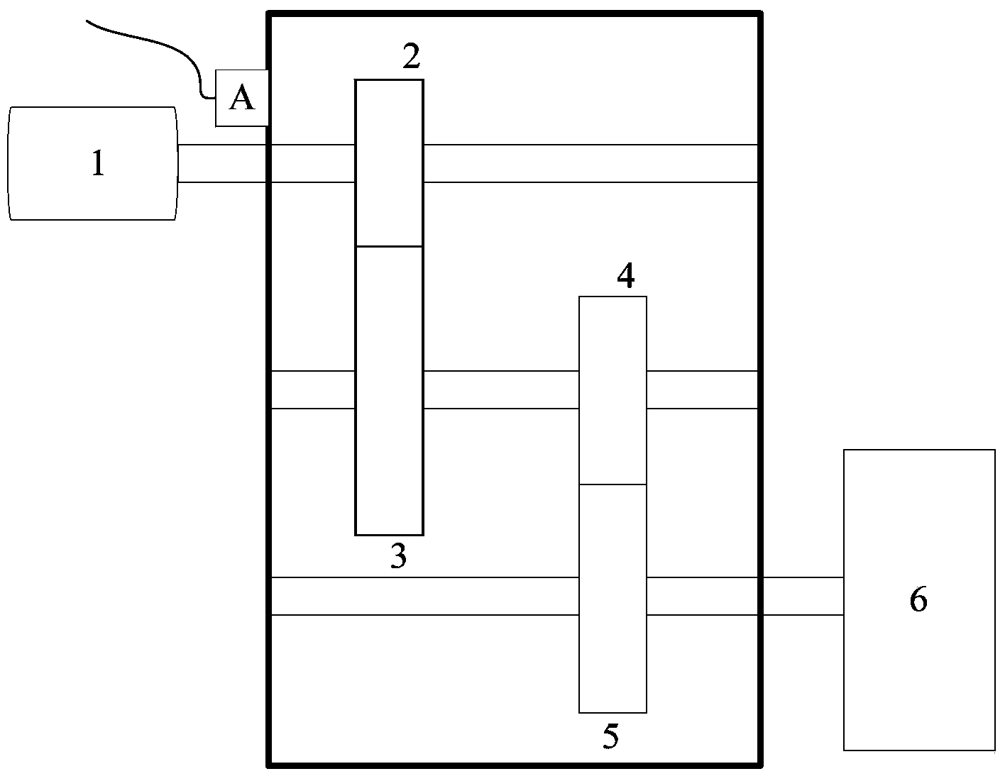
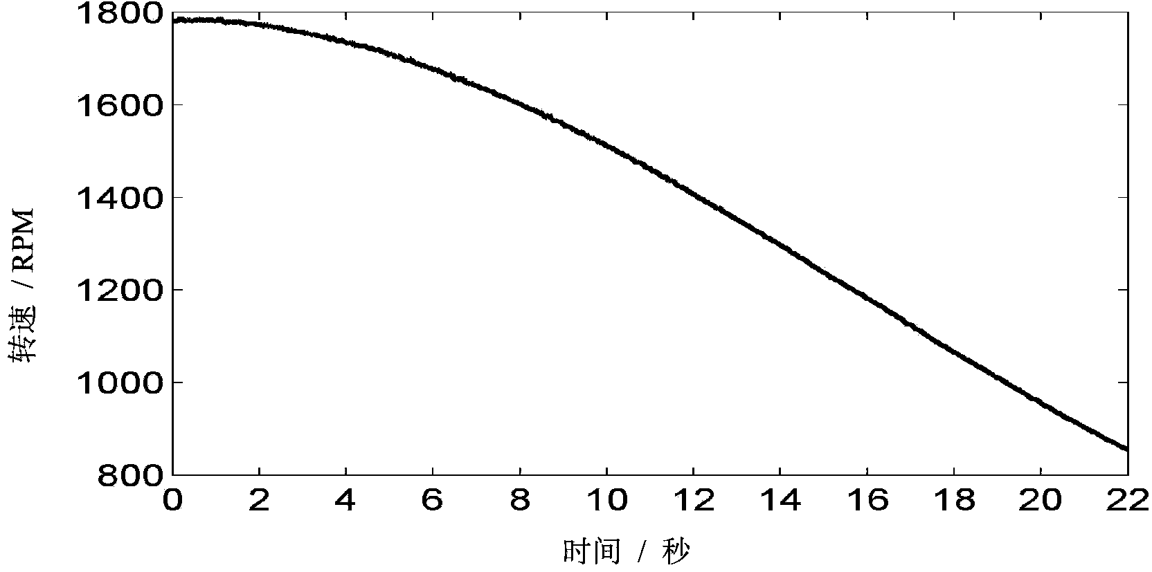
[0041] Taking the short-term phase demodulation of the gear test bench as an example during the deceleration process, the gearbox test bench is composed of a drive motor 1, a first gear 2, a second gear 3, a third gear 4, a fourth gear 5, and a brake 6 components ,Such as figure 1 As shown, the output shaft of the drive motor 1 is connected to the first gear 2, the first gear 2 meshes with the second gear 3, the second gear 3 and the third gear 4 are installed on the same transmission shaft, the third gear 4 and the fourth gear The gear 5 meshes, the transmission shaft of the fourth gear 5 is connected to the brake 6, and the first gear 2 has a peeling fault, such as figure 2 As shown, in the test, the vibration acceleration sensor A is adsorbed at the position close to the bearing end cover of the first gear 2 . In the test, the rotation speed of ...


PUM


Abstract

The present invention provides a gear case fault diagnosis method based on non-timescale short-time phase demodulation. An acceleration or speed sensor is attached to a gear case to be detected for collecting a vibration signal of the gear case to be detected. The vibration signal is subjected to short-time Fourier transform, and an instant frequency signal of characteristic vibration is obtained. The instant frequency signal is plug into generalized Fourier transform for time frequency reverse of the vibration signal. Then, a stable projection of a characteristic frequency component is abstracted by means of band-pass filtering, and subjected to generalized Fourier inverse transform, and an engagement frequency component is obtained. Thereafter, the engagement frequency component is subjected to Hilbert transform, and an instantaneous phase of the engagement frequency component is obtained. By the instant phase, angular domain re-sampling is performed on the original vibration signal, and the re-sampled signal is subjected to phase demodulation after reasonable fragmentation and angular domain average. Thus, the short-time phase demodulation is completed. The method provided by the invention can reduce the hardware cost of the detection system, and improve the market competitiveness of the detection system.

Description

technical field [0001] The invention relates to the technical field of gearbox fault diagnosis, in particular to a gearbox fault diagnosis method based on short-time phase demodulation without time scale. Background technique [0002] Partial failures of the gearbox, such as spalling and cracking of the gears, will cause a decrease in the meshing stiffness of the gears. The phase delay of the vibration signal will occur when the faulty gear meshes, and the phase change caused by the fault can be extracted through phase demodulation. Phase demodulation is more sensitive to gear imperfections than spectral analysis. Phase demodulation generally requires the gearbox to operate at a constant speed. However, the degree of phase modulation caused by faults is related to the speed. At certain speeds, the phase modulation caused by faults is not obvious, resulting in gear defects and faults that cannot be detected. The start-stop vibration signal of the gearbox contains vibration ...

Claims


Application Information

Patent Timeline
IPC IPC(8): G01M13/02
Inventor 林京赵明王琇峰徐晓强雷亚国
Owner XI AN JIAOTONG UNIV
Learn More