
Thyristor converter valve assembly

A technology for thyristor converter valves and thyristor radiators, which is applied to electrical components, electrical solid devices, semiconductor devices, etc., can solve the problems of increasing the risk of water leakage in the water system, short-circuit accidents of lower-layer electrical components, and difficulty in waterway design. The effect of water leakage risk, guaranteed service life, and reduced design difficulty

Active Publication Date: 2013-10-16
XJ ELECTRIC
View PDF4 Cites 29 Cited by
  • Summary
  • Abstract
  • Description
  • Claims
  • Application Information

AI Technical Summary

Problems solved by technology

The problem with the existing converter valve assembly is that the water cooling system adopts fully parallel water channels, which makes the design of the water channels difficult, there are many water joints, and the risk of water leakage is high. Short circuit accident; in addition, the full parallel design also requires the water cooling system to have a large water pressure, which further increases the risk of water leakage in the waterway system

Method used


Image

  • Thyristor converter valve assembly
  • Thyristor converter valve assembly
  • Thyristor converter valve assembly

Examples


Embodiment Construction

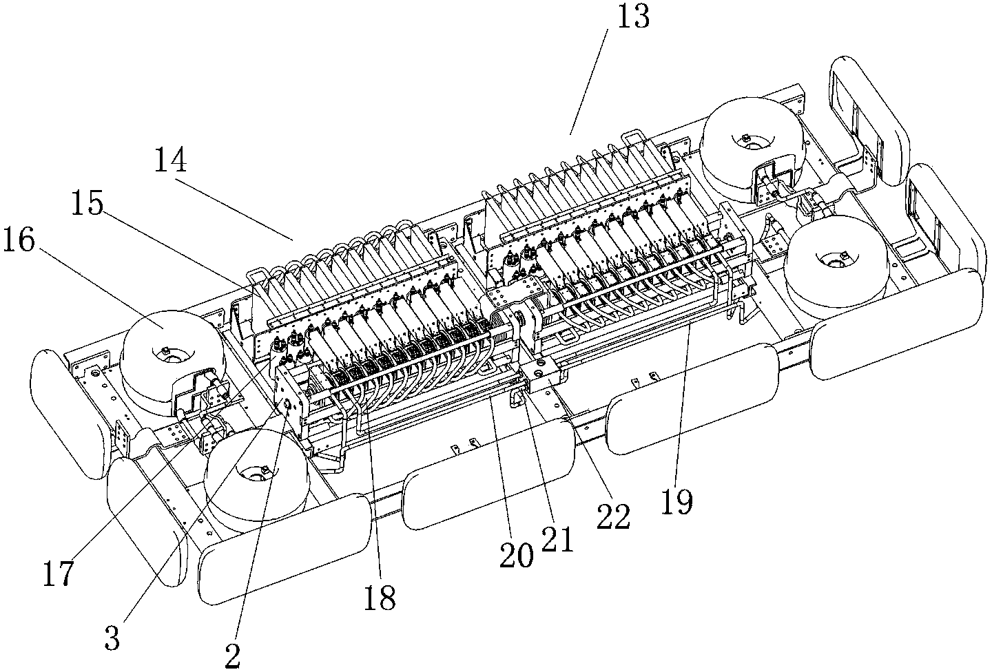
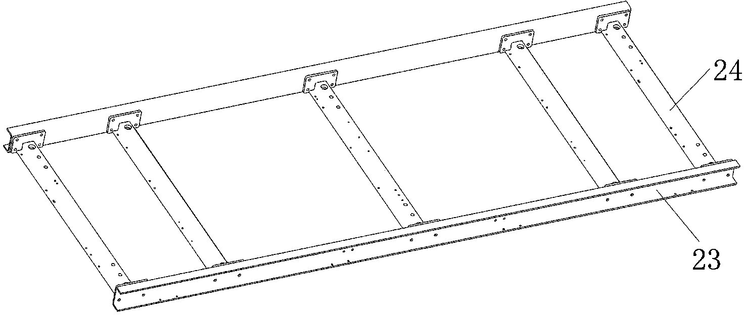
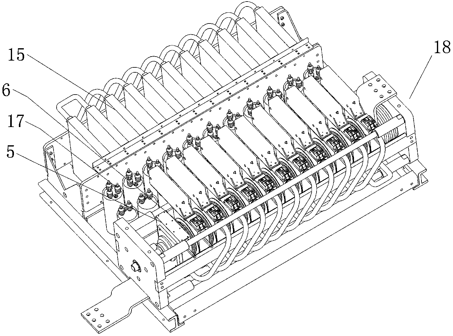
[0024] An embodiment of a thyristor converter valve assembly is Figure 1~7 Shown: including the bracket, the bracket is composed of two U-shaped insulating beams 23 arranged in parallel and a plurality of beams 24 arranged between the two U-shaped insulating beams, and the left valve unit arranged symmetrically on the left and right is arranged on the bracket 14 and the right valve unit 13, the left valve unit includes a reactor assembly 16 and a valve module, the valve module includes a valve section 18, a damping resistance unit and a damping capacitor unit, the damping capacitor unit includes a damping capacitor 17 and an insulating support, and the damping capacitor is arranged vertically upward , to facilitate the heat dissipation of the junction box of the capacitor pillar, and the damping capacitor adopts a combination of long and short structures, which can make the overall structure more compact under the condition of ensuring the electrical distance between the dampi...


PUM


Abstract

The present invention relates to a thyristor converter valve assembly. The thyristor converter valve assembly comprises a carrier on which a left valve unit and a right valve unit are arranged. Each valve unit includes reactor assemblies, resistor radiators and thyristor radiators. The thyristor converter valve assembly further comprises a water cooling system for cooling the reactor assemblies, the resistor radiators and the thyristor radiators. The water cooling system includes a main water in-coming path and a main water returning path which are communicated by a first water branch, a second water branch and a third water branch arranged in parallel. The reactor assemblies and the thyristor radiators of the left valve unit are all connected in series in the first water branch. The reactor assemblies and the thyristor radiators of the right valve unit are all connected in series in the second water branch. The resistor radiators of the left valve unit and the right valve unit are all connected in series in the third water branch. The thyristor converter valve assembly provided by the invention has a water cooling system and is simple in structure.

Description

technical field [0001] The invention relates to the field of high-power electric power electronic converter valves in power systems, in particular to a thyristor converter valve assembly. Background technique [0002] As the core component of the HVDC transmission system, the converter valve has been developed and applied for many years. Existing thyristor converter valve components such as "a new type of thyristor converter valve valve module" disclosed in Chinese patent document CN101719719A, the valve module includes a bracket, and two valve units with the same structure are arranged symmetrically on the left and right sides of the bracket , each valve unit includes a reactor assembly and a valve module, the valve module includes a valve section, a damping resistance unit and a damping capacitor unit, the damping resistance unit includes a damping resistor and a resistance radiator, the valve section includes a valve section frame, and the valve section frame includes Th...

Claims


Application Information

Patent Timeline
IPC IPC(8): H01L25/07H01L23/473
CPCH01L25/117H01L23/473H01L2924/0002
Inventor 姚为正张建肖晋杜玉格李申宋全刚王健云谢云龙
Owner XJ ELECTRIC
Learn More