
Array fiber opto-acoustic bionic ear device and signal conversion method

A hearing device and optical fiber array technology, applied in medical science, prosthesis, etc., can solve the problems of chaotic acoustic information and difficulty in obtaining pleasing sound effects, and achieve the effect of comprehensive acoustic information

Active Publication Date: 2015-05-20
济南恒大视讯科技有限公司
View PDF14 Cites 0 Cited by
  • Summary
  • Abstract
  • Description
  • Claims
  • Application Information

AI Technical Summary

Problems solved by technology

Due to the diffusion of the electric field in the electrode current, the synchronous excitation density of the stimulation current in the cochlea space is limited. Either the sound spectrum signals that originally appeared synchronously are released at intervals in time, or only the electrodes that are spaced apart in space can be selected. The spectral signals are released at the same time, so as to reduce the mutual interference of electric fields caused by the simultaneous release of adjacent electrode currents. Therefore, the adjustments made when these electrical signals are excited cause some distortions in the original spectrum array structure of the sound during the stage of stimulating the auditory nerve. For speech signals whose time and spectral structure change slowly, the influence may be limited, and it will not significantly affect the recognition and understanding of the transmitted speech, but for music signals whose spectral structure and temporal relationship change more closely, this distortion It will lead to the confusion of the acoustic information, making it difficult to obtain pleasant sound effects

Method used


Image

  • Array fiber opto-acoustic bionic ear device and signal conversion method
  • Array fiber opto-acoustic bionic ear device and signal conversion method
  • Array fiber opto-acoustic bionic ear device and signal conversion method

Examples


Embodiment Construction

[0038] The utility model is described in detail below in conjunction with accompanying drawing:

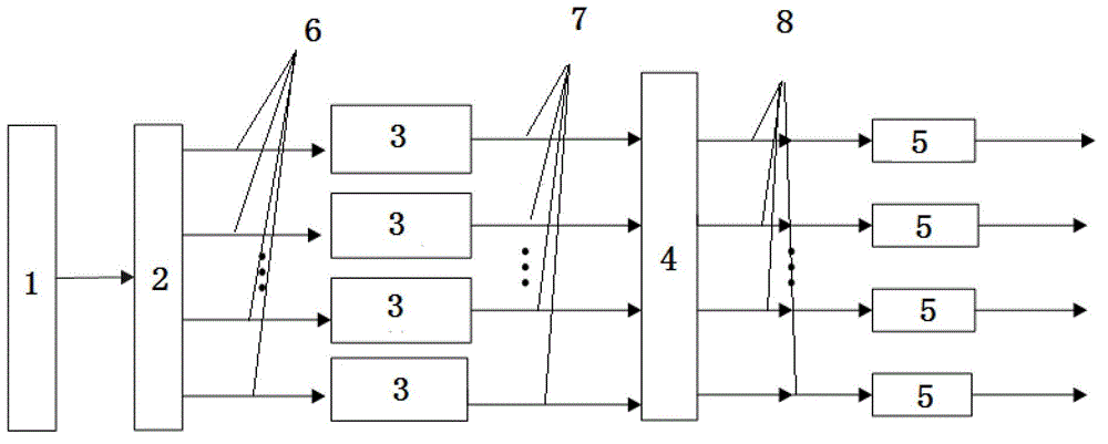
[0039]As a necessary device for array fiber laser to induce hearing, a signal device that can generate array fiber laser signals and then excite animal auditory front ganglion bundles (or arrays) is needed to induce the auditory response corresponding to the auditory functional area of ​​the brain. The utility model proposes a laser-induced auditory light signal generating device that drives an array light source with multiple electrical signals to generate an array fiber optical pulse 7 signal, and then stimulates the emission of auditory nerves.

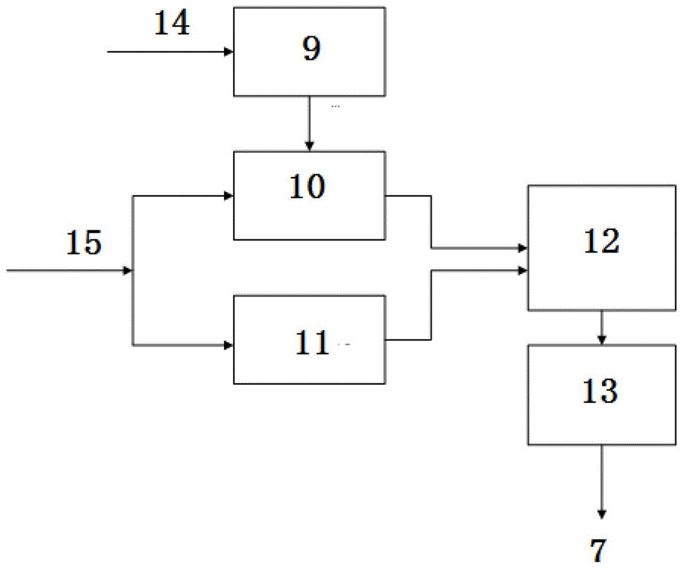
[0040] The array optical signal generation system used to stimulate the auditory nerve bundle consists of five parts, such as figure 1 As shown, it includes voice processor 1, array data controller 2, laser modulation driver 3 (including power supply unit 14, LD controllable constant current drive unit 10, pulse timing control unit 11...


PUM


Abstract

The invention particularly discloses an array fiber opto-acoustic bionic ear device and a signal conversion method. The device comprises a sound signal processor, an array data controller, laser modulation drivers, a laser fiber array and fiber collimators, wherein the laser modulation drivers are in charge of converting multiple signals output by the sound signal processor into corresponding optical signals; the sound signal processor is connected with the array data controller; the array data controller respectively controls all electrical signals to be connected with the corresponding laser modulation drivers; the laser modulation drivers are connected with the fiber array; the fiber array is connected with the corresponding fiber collimators; finally, each optical signal is output to irradiate corresponding positions of the auditory nerves of living bodies. Optical signal outputs of all ports of the laser fiber array respectively correspond to audio ranges divided by the logarithmic scale, that is, each fiber signal output corresponds to one corresponding audio range signal.

Description

technical field [0001] The invention relates to the application field of optical fiber sensing and photoelectric technology, in particular to an array optical fiber laser-induced auditory device and an optical signal conversion method. Background technique [0002] The sensory sound of the inner ear of the auditory system has the characteristics that the topological structure of the cochlea and the frequency components of the sound correspond to each other, and a large number of auditory cells (also known as hair cells) are distributed in the interior according to the corresponding positions, and their functions are similar to "sensors" for sensing audio components. It is these hair cells and the auditory nerve at the back end that are connected to each other to complete the transmission of sound information to the functional areas of the brain. The existing artificial auditory reconstruction device - Cochlear Implant (Cochlear Implant, often referred to as CI), is based on ...

Claims


Application Information

Patent Timeline
Patent Type & Authority Patents(China)
IPC IPC(8): A61F2/18
Inventor 田岚王静轩卓壮常军张飒飒李晨陆冬雨
Owner 济南恒大视讯科技有限公司
Learn More