Tool for cleaning wire rope

A technology for cleaning tools and wire ropes, applied in cleaning methods and utensils, cleaning methods using tools, cleaning flexible objects, etc., can solve problems such as increased viscosity and inability to cope with ropes

Inactive Publication Date: 2013-10-23
MITSUBISHI ELECTRIC CORP +1
View PDF8 Cites 13 Cited by
  • Summary
  • Abstract
  • Description
  • Claims
  • Application Information

AI Technical Summary

Problems solved by technology

[0005] In the wire rope cleaning tool disclosed in Patent Document 1, since accumulated grease overflows and falls from the wiper, recovery work is required, which is particularly problematic when applied to wire ropes used in elevators installed in high-rise buildings.
In addition, there is a problem of being unable to cope with stretched ropes and grease with significantly increased viscosity.

Method used


Image

  • Tool for cleaning wire rope
  • Tool for cleaning wire rope
  • Tool for cleaning wire rope

Examples


Embodiment approach 1

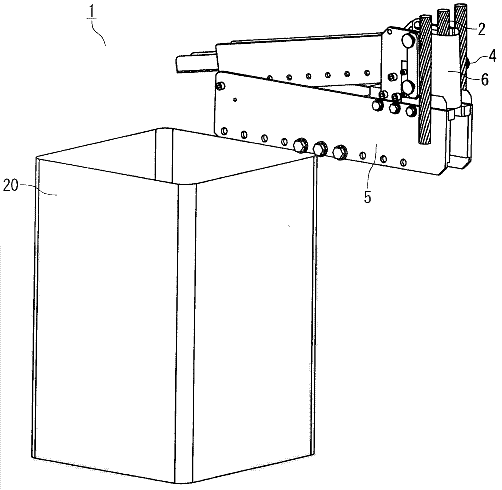
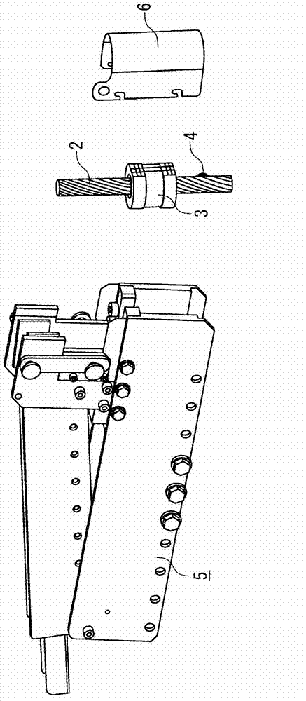
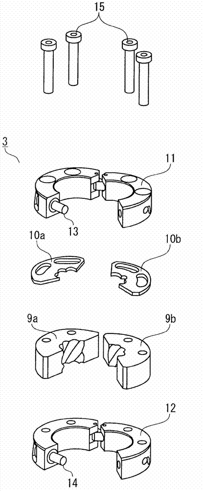
[0026] Embodiment 1 relates to a wire rope cleaning tool. The wire rope cleaning tool is composed of a wiper assembly, a rotary support member, a scraper, and a cover. The wiper assembly is composed of a resin wiper, a metal plate, and upper and lower reinforcement members. The resin The wiper has an inner surface that imitates the twisting of a steel wire rope, and is cut by a face offset from the center by a certain distance and parallel to the central axis of the steel wire rope; The inner peripheral shape of the upper and lower reinforcing members fixes the resin wiper and the metal plate by compressing the resin wiper and the metal plate in the up-down and center directions, and is cut off by a surface offset from the center by a certain distance; the rotation support The member supports the rotation of the wiper assembly; the scraper scrapes the grease attached to the wire rope.

[0027] Below, based on a perspective view of a wire rope cleaning tool figure 1 , as the ...

Embodiment approach 2

[0071] The wire rope cleaning tool of the second embodiment is a wire rope cleaning tool in which a cover plate is provided on the scraper of the wire rope cleaning tool of the first embodiment.

[0072] Below, the enlarged view based on the scraper of the wire rope cleaning tool is Figure 15 , the configuration and function of Embodiment 2 of the present invention will be described centering on the difference (cover plate) from the wire rope cleaning tool of Embodiment 1.

[0073] In addition, in Figure 15 In the same way as in Embodiment 1 figure 2 , Figure 11 The same reference numerals are attached to the same or corresponding parts.

[0074] Such as Figure 15 As shown, a cover plate 41 is provided above the vicinity of the overlapping section of the squeegee 7 . In addition, the bottom surface of the scraper 7 and the guide groove 8 , the side wall, and the inner surface of the cover plate 41 are coated with a low coefficient of friction by, for example, Teflon ...

Embodiment approach 3

[0079] The wire rope cleaning tool of Embodiment 3 is formed by forming the wiper assembly of Embodiment 1 into such a structure that a resin wiper and a metal plate are sandwiched between annular first and second reinforcement members, and A leaf spring is provided between the inner peripheral sides of the first and second reinforcement members and the outer peripheral side of the resin wiper, and is compressed in vertical and central directions.

[0080] Hereinafter, centering on the wiper assembly, which is the difference from Embodiment 1, based on a perspective view of the components of the wiper assembly, that is, Figure 16 , to describe the structure and function of Embodiment 3 of the present invention.

[0081] The wiper assembly 50 is composed of a pair of resin wipers 51a, 51b (hereinafter collectively referred to as resin wiper 51), a pair of metal plates 52a, 52b (hereinafter collectively referred to as metal plate 52), and The first reinforcement member 53 and ...


PUM


Abstract

The invention provides a tool for cleaning wire ropes, wherein the tool is capable of dealing with elongated wire ropes and lubricating grease with high viscosity, and performing continuous cleaning. The tool is composed of a wiper assembly part (3), a rotation supporting member (26), a scraper plate (7), and a cover. The wiper assembly part comprises a resin wiper (9), a metallic plate (10), and strengthening members (11, 12). The resin wiper (9) comprises an inner surface simulating a twisted wire rope (2) and is cut by a surface. The surface is biased from the center with a certain distance and is in parallel with a central shaft. The metallic plate (10) is disposed on the upper end face of the resin wiper and comprises an inner circumference larger than the external diameter of the wire rope. The strengthening members (11, 12) compress the resin wiper respectively from the up and down direction and the central direction. The rotation supporting member supports the rotating wiper assembly part. The scraper plate is close to the wire rope and is arranged on the upper end face of the wiper assembly part in order to scrape lubricating grease (4) on the wire rope. The cover covers the wiper assembly part and the scraper plate so that the wire rope is relatively moved from the metallic plates to the resin wiper.

Description

technical field [0001] The present invention relates to a wire rope cleaning tool for removing excess deposits on the surface of a wire rope represented by grease used for rust prevention and wear prevention of the wire rope with good workability. Background technique [0002] Steel wire ropes used in elevators, etc. need to periodically remove and clean grease and deposits that exist on the surface for rust prevention and wear prevention. [0003] As a conventional wire rope cleaning tool, it is disclosed that a resin wiper having a notch and the inner peripheral surface of the hole is a shape imitating twisting of strands on the surface of the rope is attached to the rope, and placed on a rotating support plate. A cleaning tool used in the state (for example, refer to Patent Document 1). [0004] Patent Document 1: Japanese Patent Laying-Open No. 2003-190888 (paragraphs [0045] to [0052] and Figure 5 ) [0005] In the wire rope cleaning tool disclosed in Patent Document ...

Claims


Application Information

Patent Timeline
Patent Type & Authority Applications(China)
IPC IPC(8): B08B1/00B08B1/04
CPCB08B1/005B08B1/02B08B1/04B08B11/00B66B7/12
Inventor 吉冈孝宫本佳典本石直弘藤井幸广明石正雄
Owner MITSUBISHI ELECTRIC CORP
Why Eureka
Try Eureka