Method for continuous casting by using continuous casting dummy bar assembly and continuous casting dummy bar assembly

An assembly and continuous casting technology, which is applied in the field of continuous steel casting, can solve the problems of incomplete primary slab shell, production accidents that cannot be pulled, and roller jamming, etc., and achieve the effects of simple structure, reduced production cost, and reduced quantity used

Active Publication Date: 2013-10-23
HENGYANG VALIN STEEL TUBE
View PDF11 Cites 12 Cited by
  • Summary
  • Abstract
  • Description
  • Claims
  • Application Information

AI Technical Summary

Problems solved by technology

The problems of the above method are: the thin iron tube cannot be completely melted after pouring, and it is easy to scratch the inner wall of the copper tube of the crystallizer; the steel bar section will not be completely wrapped by the molten steel, and the shell of the primary billet

Method used


Image

  • Method for continuous casting by using continuous casting dummy bar assembly and continuous casting dummy bar assembly
  • Method for continuous casting by using continuous casting dummy bar assembly and continuous casting dummy bar assembly
  • Method for continuous casting by using continuous casting dummy bar assembly and continuous casting dummy bar assembly

Examples


Embodiment Construction

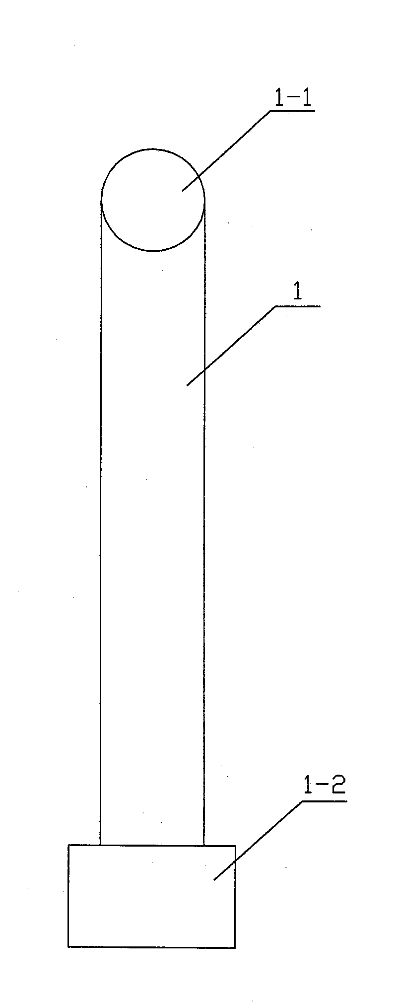
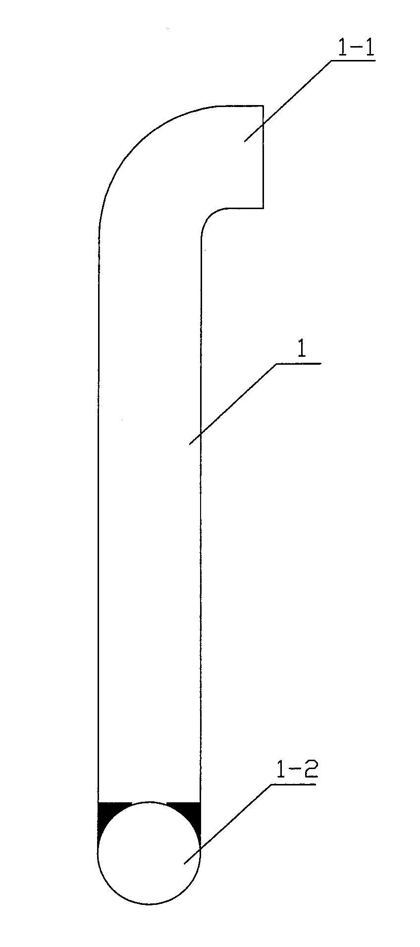
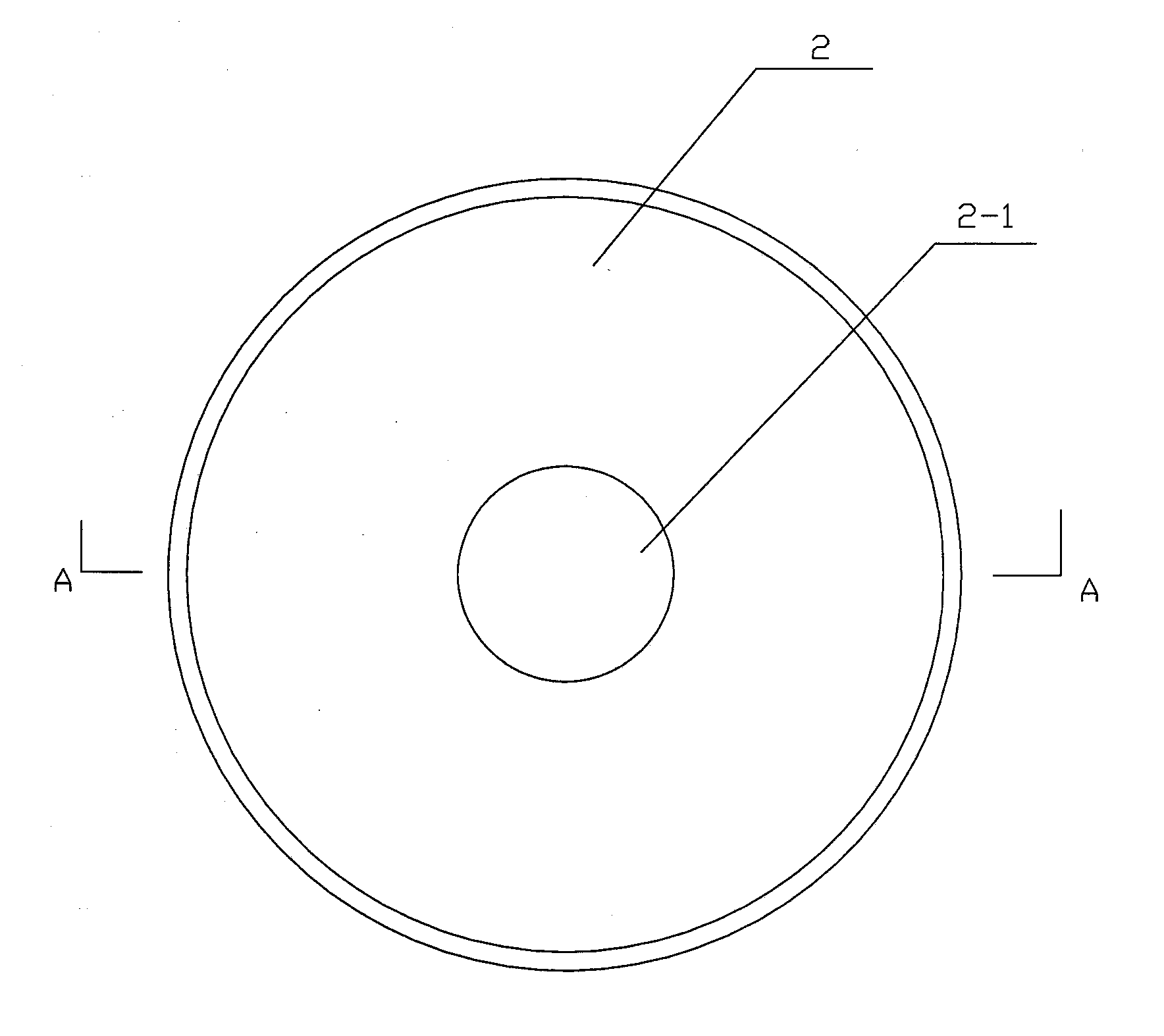
[0024] A method for continuous casting using a continuous casting dummy assembly, the continuous casting dummy assembly includes a dummy hook 1, a baffle plate 2 and a cooling cage 3, and the continuous casting dummy assembly is used for continuous casting At the same time, the dummy head 4 is first sent into the second cold room, and then the lower end of the dummy hook 1 and the cross bar 1-2 are put into the opening groove 4-1 of the dummy head 4, and then the dummy head 4 continues to enter the crystallization For the position required by the dummy section of copper tube 5 of the dummy, use asbestos rope 8 to block the gap between the dummy head 4 and the mold copper tube 5, lay the first layer of iron shot 6 on the dummy head 4, and the first layer of iron The surface of the shot 6 forms a slope matching the dummy head 4 . The baffle plate 2 passes through the elbow 1-1 at the upper end of the dummy hook 1 and is placed on the first layer of iron shot layer 6 of the dummy...


PUM


Abstract

The invention relates to a method for continuous casting by using a continuous casting dummy bar assembly. The continuous casting dummy bar assembly comprises a dummy bar hook, a baffle and a chill cage. When the continuous casting dummy bar assembly is used for performing continuous casting, a dummy bar head is firstly fed into a secondary cooling chamber, the lower end of the dummy bar hook and a cross bar are installed in an open slot of the dummy bar head, then the dummy bar head continuously enters a process required position of a dummy bar section of a mold copper pipe, an asbestos rope is used for blocking a gap between the dummy bar head and the mold copper pipe, a first iron shot layer is laid on the dummy bar head, the baffle penetrates through the first iron shot layer at the dummy bar head from a penetrating head at the upper end of the dummy bar hook, a second iron shot layer is laid on the baffle, the chill cage is put in the center of a dummy bar chamber formed by the dummy bar head and the mold copper pipe, and finally a certain quantity of deformed steel bars are inserted into the chill cage. Casting is started after the continuous casting dummy bar assembly is installed, molten steel forms a blank head which is connected with the dummy bar head and the continuous production of casting blanks is realized under the traction of a withdrawing and straightening machine.

Description

technical field [0001] The invention relates to the technical field of continuous casting steel, in particular to a sealing and starting ingot process before continuous casting, which is suitable for the production of continuous casting slabs with smaller specifications. Background technique [0002] Before the arc continuous casting machine casts steel, the dummy bar sends the dummy head to the position required by the dummy section of the mold copper tube in the crystallizer, and then uses asbestos rope and other materials to seal the gap between the dummy head and the copper tube , put the cooling material into the dummy cavity composed of the dummy head and the copper tube. When pouring, the molten steel quickly fills the copper tube. The cooling material in the dummy cavity accelerates the solidification of the molten steel, forming the connection between the billet head and the dummy head. Under the traction of the tension leveler, the continuous production of cast sla...

Claims


Application Information

Patent Timeline
IPC IPC(8): B22D11/08
Inventor 李卫平吕士忠孙群保田汉蒲贺江明黄永锋付剑
Owner HENGYANG VALIN STEEL TUBE
Why Eureka
Try Eureka