
Combined type shield tunneling machine

A shield machine and compound technology, applied to mining equipment, earthwork drilling, tunnels, etc., can solve the problems of reducing construction efficiency, increasing tool change frequency, shortening service life, etc., to improve construction efficiency, simplify configuration, extend The effect of service life

Active Publication Date: 2013-10-23
CHINA RAILWAY ENGINEERING EQUIPMENT GROUP CO LTD
View PDF5 Cites 27 Cited by
  • Summary
  • Abstract
  • Description
  • Claims
  • Application Information

AI Technical Summary

Problems solved by technology

Thus affecting the rock-breaking effect of the disc hob, shortening its service life, increasing the frequency of tool change, and reducing construction efficiency

Method used


Image

  • Combined type shield tunneling machine
  • Combined type shield tunneling machine
  • Combined type shield tunneling machine

Examples


Embodiment approach 1

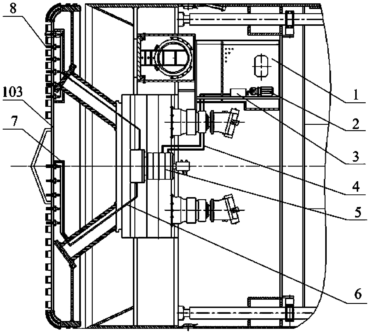
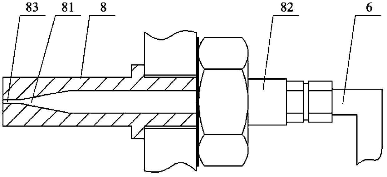
[0041] Please refer to Figure 1 to Figure 4 , figure 1 It is a structural schematic diagram of a compound shield machine with a high-pressure fluid jet grooving device according to the first embodiment of the present invention; figure 2 for figure 1 The enlarged schematic diagram of area A in the middle; image 3 It is a schematic diagram of the nozzle structure in the first embodiment of the present invention; Figure 4 Schematic diagram of the high-pressure fluid jet grooving trajectory.

[0042] The high-pressure fluid jet slotting device is arranged at the front of the shield body 101 for jetting high-pressure fluid to the front of the shield body 101 in the same direction as the shield body 101 advances.

[0043] The high-pressure fluid jet grooving device provided in this embodiment includes a liquid storage tank 1, a pump 2, a booster 3, a first pipeline 4, a central rotary joint 5, a second pipeline 6, a sheath 7 and a nozzle 8, The components are sequentially c...

Embodiment approach 2

[0063] Image 6 It is a partial structural schematic diagram of a composite shield machine with an abrasive high-pressure fluid jet grooving device according to the second embodiment of the present invention; Figure 7 for Image 6 An enlarged schematic view of the structural details of the nozzle and the abrasive supply device in area B of ; Figure 8 for Figure 7 An enlarged schematic view of the structural details of the abrasive suction pipe and the abrasive throttle cock in middle region C; Figure 9 It is a schematic diagram of the nozzle structure in the second embodiment of the present invention.

[0064] This embodiment describes a high-pressure plunger pump directly driven by a drive motor and an abrasive high-pressure fluid jet grooving composite shield machine. The high-pressure fluid is a mixture of high-pressure water and abrasive, and the nozzle is an abrasive with an abrasive mixing function. Mixing nozzle 14.

[0065] Such as Image 6 As shown, the abra...


PUM


Abstract

The invention discloses a combined type shield tunneling machine which comprises a shield body and a cutter disc arranged at the front end of the shield body. The combined type shield tunneling machine further comprises a high-pressure fluid jet grooving device. The high-pressure fluid jet grooving device comprises a liquid storage bin, a pressurization mechanism and a plurality of nozzles, wherein fluid for jetting is contained in the liquid storage bin, the pressurization mechanism is used for pressurizing the fluid and is communicated with the liquid storage bin, the pressurization mechanism is communicated with a central rotary connector through a first pipeline, the nozzles are arranged on the cutter disc, and the nozzles are communicated with the central rotary connector through a second pipeline. When the combined type shield tunneling machine handles a loose ground, cutting can be directly carried out through cutters and other mechanical cutters, the cutting can be carried out by combining high-pressure fluid jetting and a mechanical cutter, and the phenomena that in the prior art, a combined type shield tunneling machine is provided with a disc-shaped rolling cutter, the disc-shaped rolling cutter is blocked and eccentrically worn, and muck forms mud cakes on a cutter ring are avoided.

Description

technical field [0001] The invention relates to the technical field of shield machines, in particular to a compound shield machine. Background technique [0002] The shield machine is a special construction machine for tunneling, and the compound shield machine is suitable for constructing tunnels in the composite stratum with uneven hardness and softness formed by the interaction of clay, sandy soil, weathered rock, and gravel and pebble strata. , including at least the cutter head and the shield body. The shield body can be roughly divided into three parts: the front shield, the middle shield and the tail shield. The cutter head and the various knives installed on it are located at the front end of the shield machine close to the excavation surface. In the existing composite shield machine, the cutter head is equipped with cutting knives and scrapers suitable for soft soil cutting, and a disc-shaped hob suitable for hard rock crushing. When this compound rock-breaking cu...

Claims


Application Information

Patent Timeline
Patent Type & Authority Applications(China)
IPC IPC(8): E21D9/08E21D9/04
CPCE21D9/06E21D9/0879E21D9/1066E21D9/08E21D9/087E21D9/1006E21D9/112
Inventor 何於琏李建斌
Owner CHINA RAILWAY ENGINEERING EQUIPMENT GROUP CO LTD
Learn More