LED projection lamp

A technology of LED projection lamps and LED modules, which is applied to lighting devices, cooling/heating devices of lighting devices, light sources, etc., and can solve the problem of excessive heat accumulation, inability to dissipate heat effectively, and affecting the reliability and life of LED projection lamps and other issues to achieve the effect of efficient heat exchange and excellent heat dissipation

Inactive Publication Date: 2015-06-17
ZHONGSHAN WEIQIANG TECH CO LTD
View PDF6 Cites 0 Cited by
  • Summary
  • Abstract
  • Description
  • Claims
  • Application Information

AI Technical Summary

Problems solved by technology

The application of LED projection lamps is more diverse, so its irradiation direction is also required to be more flexible. It is often necessary to adjust the irradiation direction according to the site or real-time needs. When the LED projection lamp is illuminated in different directions, it will inevitably affect the heat generated. The transmission path is affected. In severe cases, the heat cannot be dissipated effectively in some directions, and the heat accumulates too much, which will affect the reliability and life of the LED projection lamp.

Method used


Image

  • LED projection lamp
  • LED projection lamp
  • LED projection lamp

Examples


Embodiment Construction

[0042] The idea, specific structure and technical effects of the present invention will be clearly and completely described below in conjunction with the embodiments and accompanying drawings, so as to fully understand the purpose, features and effects of the present invention. Apparently, the described embodiments are only some of the embodiments of the present invention, rather than all of them. Based on the embodiments of the present invention, other embodiments obtained by those skilled in the art without creative efforts belong to The protection scope of the present invention.

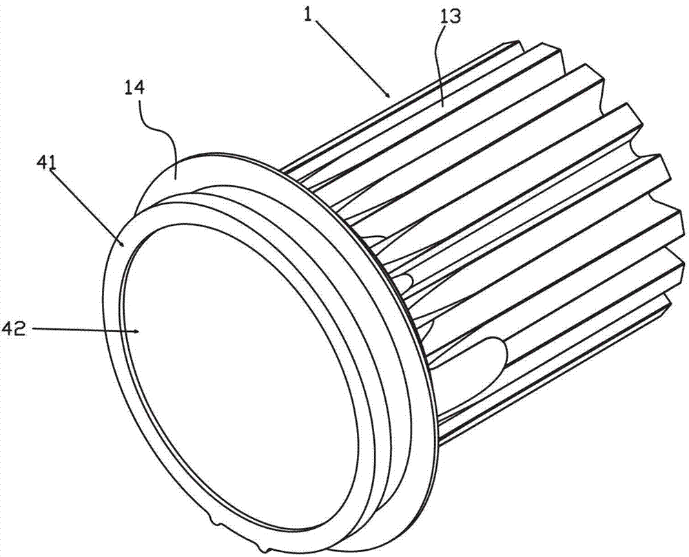
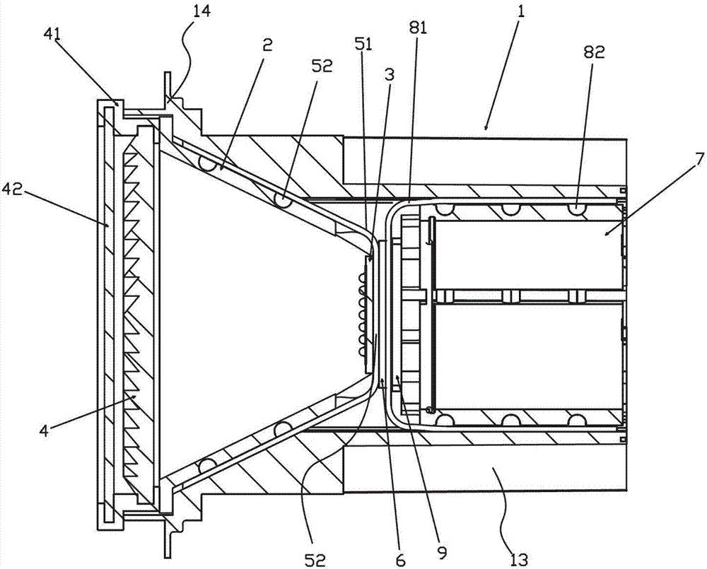
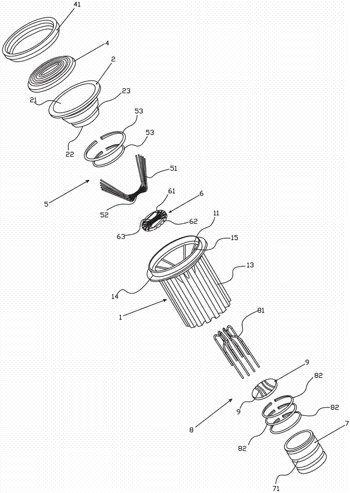
[0043] refer to figure 1 , figure 2 and image 3 , The main structure of the LED projection lamp of the present invention includes a heat sink 1 , a lamp cup 2 , an LED module 3 , a lens 4 , a first heat conduction group 5 , a fixing plate 6 , a fixing device 7 and a second heat conduction group 8 .

[0044] The cooling device 1 is in a cylindrical shape, such as Figure 4As shown, the heat...


PUM


Abstract

The invention discloses an LED projection lamp which comprises a cylindrical heat dissipation device, a lamp cup, an LED module, a lens, a first heat conduction set, a fixing device and a second heat conduction set, wherein the cylindrical heat dissipation device is provided with a horn-shaped inner chamber at the front end inside the inner chamber of the heat dissipating device and a cylindrical inner chamber at the rear end inside the inner chamber of the heat dissipating device; the lamp cup is arranged inside the horn-shaped inner chamber; the LED module is positioned at the small opening part of the lamp cup; the lens is used for light-transmitting of the LED module; the first heat conduction set comprises a plurality of U-shaped first heating pipes, U-shaped middle sections of the U-shaped first heating pipes form a smooth face for supporting the LED module, and the U-shaped ends are positioned between the outer wall of the lamp cup and the wall surface of the horn-shaped inner chamber and jointed mutually; the fixing device is sleeved with the rear end of the cylindrical inner chamber; the second heat conduction set comprises a plurality of U-shaped second heating pipes, the U-shaped middle sections of the heating pipes are in contact with the U-shaped middle sections of the first heating pipes, and the U-shaped ends of the second heating pipes are sleeved with the outer side of the fixing device and are in fit with the cylindrical inner chamber. According to the invention, mutual matching of the two heat conduction sets are adopted so as to enable the heat conduction efficiency of the LED projection lamp to be kept in a sufficient height and ensure that the LED lamp irradiates in any directions, and the two heat conduction sets have excellent heat dissipation effects.

Description

technical field [0001] This application is a divisional application of the patent (patent name: an LED projection lamp, application date: 2012-03-02, application number: 201210052973.0). technical field [0002] The invention relates to a spotlight, in particular to an LED projection lamp. Background technique [0003] LED projection lamps are also called linear LED projection lamps, etc. Because of their long strip shape, some people call them LED line lamps. They are mainly used for venue and architectural decoration lighting, and to outline the outline of buildings and venues. The application of LED projection lamps is more diverse, so its irradiation direction is also required to be more flexible. It is often necessary to adjust the irradiation direction according to the site or real-time needs. When the LED projection lamp is illuminated in different directions, it will inevitably affect the heat generated. The transmission path is affected, and in severe cases, the ...

Claims


Application Information

Patent Timeline
Patent Type & Authority Patents(China)
IPC IPC(8): F21S8/00F21V29/71F21Y101/02F21V29/51F21V29/77F21V29/83
Inventor 李克勤陈宏杰
Owner ZHONGSHAN WEIQIANG TECH CO LTD
Why Eureka
Try Eureka