Connecting device for kill/choke lines between a riser and a floating drilling vessel

a technology of connecting device and riser, which is applied in the direction of earth drilling, drilling machines and methods, and fluid removal, etc., can solve the problems of insufficient compensation of vertical relative movements, and achieve the effect of improving the stability of the bore hole wall and improving the hole to manage the pressur

Active Publication Date: 2012-12-20
FUTURE PROD
View PDF16 Cites 34 Cited by
  • Summary
  • Abstract
  • Description
  • Claims
  • Application Information

AI Technical Summary

Benefits of technology

[0001]This invention relates to a connecting device for kill- and choke hoses at a riser. More specifically it relates to a remote controlled automatic connecting device for kill- and choke hoses between a riser and their adjacent kill- and choke flexible housings from a kill / choke manifold at a rig. A first advantage of the invention is that it facilitates the connecting process due to the horizontal operation instead of the vertical operation wherein the risers pendulum movement otherwise makes the connecting less secure. A second advantage of the invention is that the operator may stand on a place at a distance from the riser and target in and remote-control the connection in a way that one may avoid any operator to hang in riding belts. The operation becomes more secure to the operator and safer due to the easier targeting of the connecting manifold to the riser's kill / choke manifold, in addition the connection may be conducted faster.
[0002]Some Background Information: a Short Overview of Marine Drilling for Oil
[0003]During marine drilling, for instance during drilling of exploration wells or production wells, it is placed a drilling template or template at the sea-floor, wherein one usually first drill a pretty shallow 36″ borehole and lines with a 30″ casing, a so-called conductor casing. Both the drill pipe and the casings are put together by screwing by help of a top drive drilling motor in a drawwork, for instance hanging in the crown block in an regular drilling derrick or in the spreader at a hydraulic Ram Rig and getting lowered through the drilling template or the template. So one may get a stable top section of the well for further drilling and one may prevent earth fall into the well and one prevents to go beyond the pressure of the ambient relatively uncompacted or unconsolidated sediments, which have a low fractionating pressure so close to the surface. By this initial drilling a relative thin slurry which is not returned to the drilling platform at the sea surface is used. Further it is drilled with a 26″ bit through the conductor casing and thereafter it's used a casing of 20″ mainly in the whole length of the drilled hole, the conductor casing included. This improves the stability of the bore hole wall against fractioning to deeper brehole depths, at the same time as one improves the hole to manage higher pressure from the return sludge when a riser arrives later on. Neither when drilling with 26″ bit it is used a heavy drilling mud, but a relative thin slurry. The drill string comprise a bit inclusive a so called “bottom hole assembly” BHA in the bottom end of multiple drill pipes which are screwed together. BHA comprises a drill collar and a possible drilling instrumentation. The drill pipes have a narrower diameter than the bit. It is the drill collar that provides the essential weight of the bit against the bottom of the hole during drilling. The weight of the bore hole is being compensated by the crown block so that the drill string is upheld and prevents that it buckles in the well.The Riser
[0004]When the 20″ casing is inserted into the well there is a blow out valve BOP and a riser (1) at the top of this to be installed via a ball joint at the BOP. Kill- and choke-hoses passing the ball joint may be coiled up some few turns to stand the torsion movements up to about 4 degrees in the ball joint. The blow out valve is installed at the well head which is comprised of the top-part of the installed casing pipes in the template, the one inside the previous, usually 30″ and 20″ casings. The blow out valve BOP is skidded in at a sledge (59) in the moonpool at a cellar 
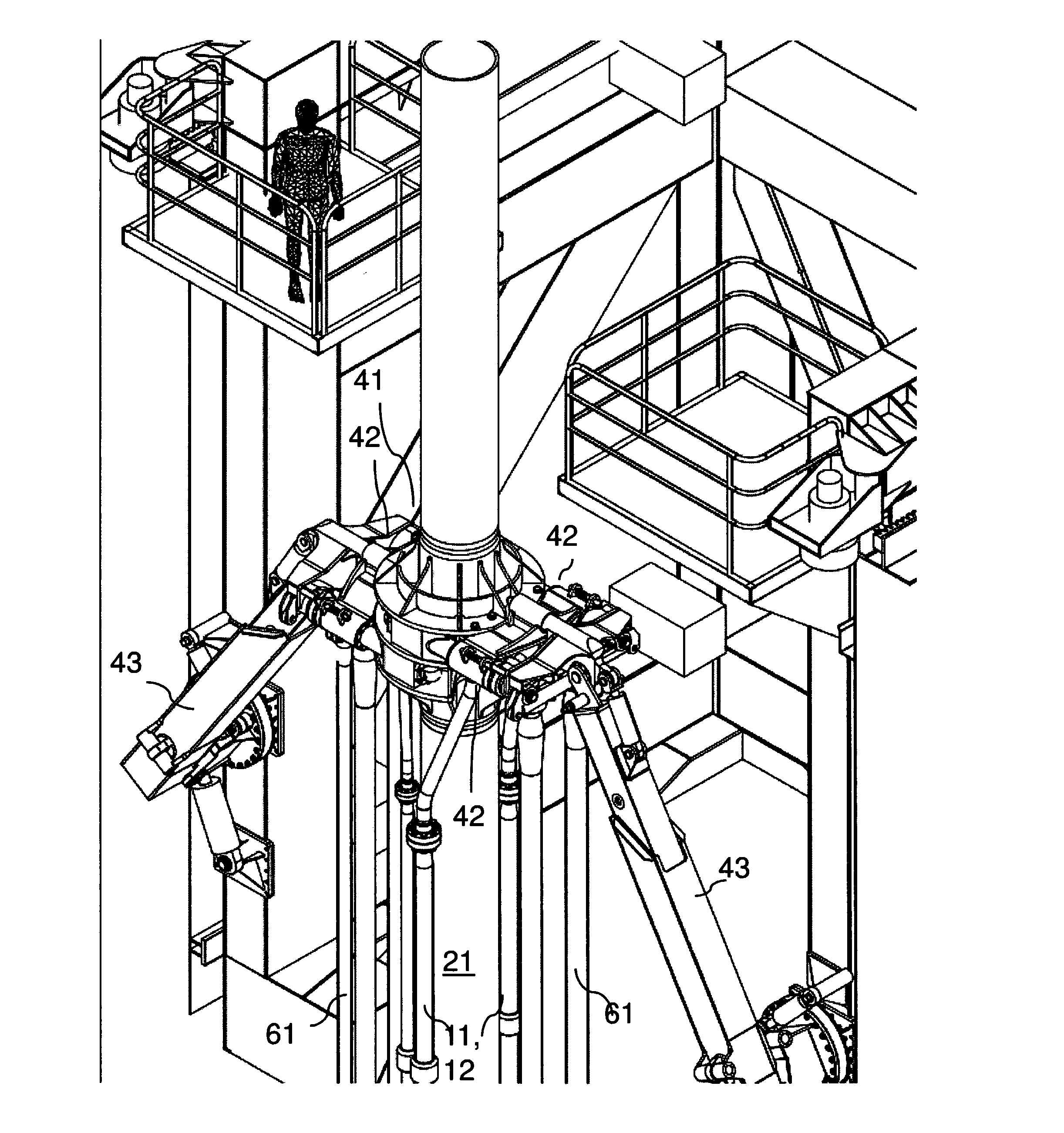
deck (58) under the rig floor (55) and thereafter is mounted, one by one, riser sections (13) by use of their lower flange connector (132) in the top of every hanging riser line (1) hanging in slips (56) in the rig floor (55). The connected riser line (1) may then be lowered further by using the crown block or the spreader in the drilling derrick, and be lowered, section by section, until a desired depth is reached, as the BOP reaches the well head. This process terminates by installing a so-called slip joint (2) on top of the upper so-called landing string (60). This has to take place outside the template to prevent a catastrophe if one should lose and drop the riser string at the template. Then the BOP and the riser is swung in over the template and the BOP is lowered down to the well head when the BOP is in the correct position on top of this, and is locked by, special purpose hydraulic mechanisms.
[0005]
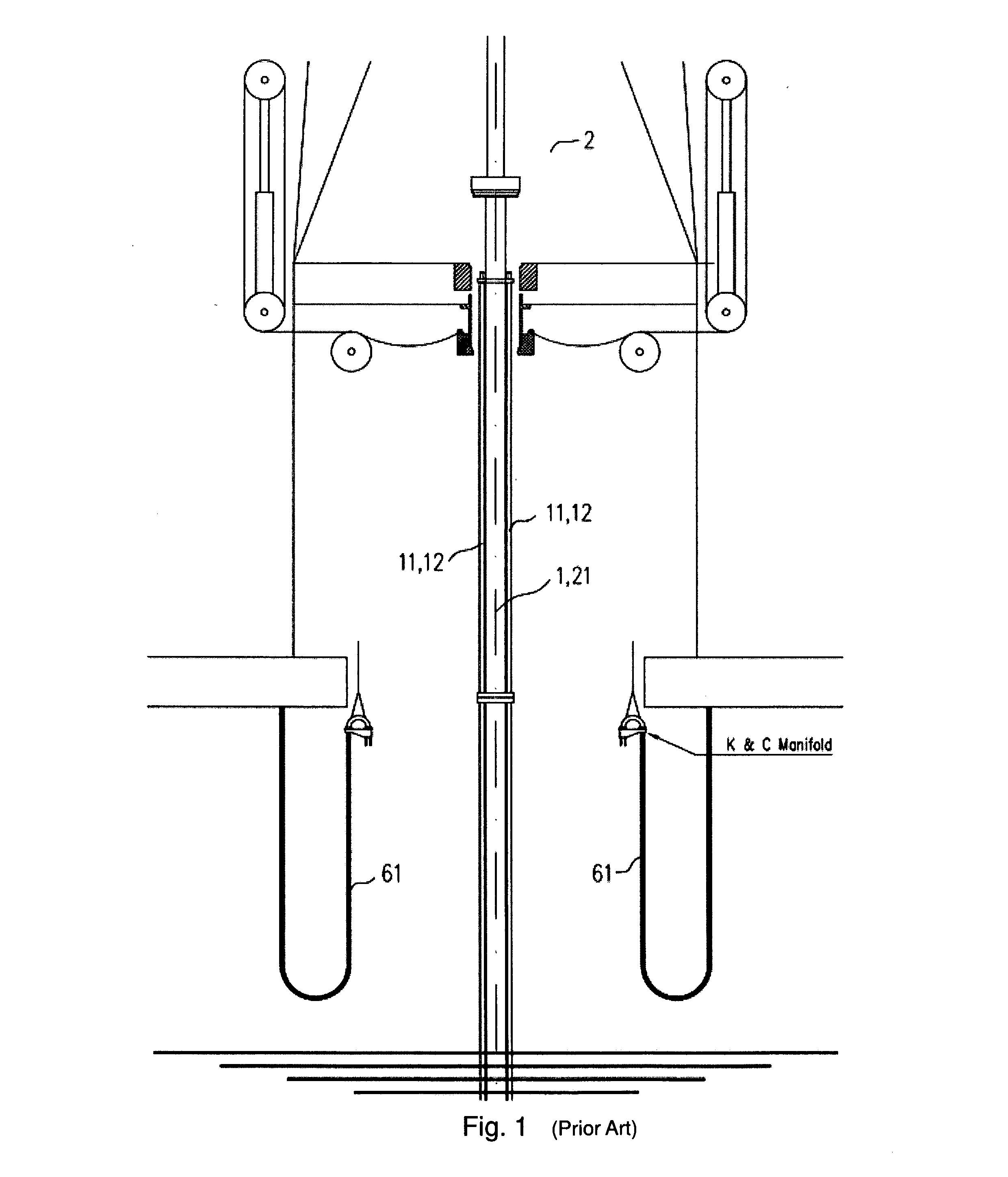
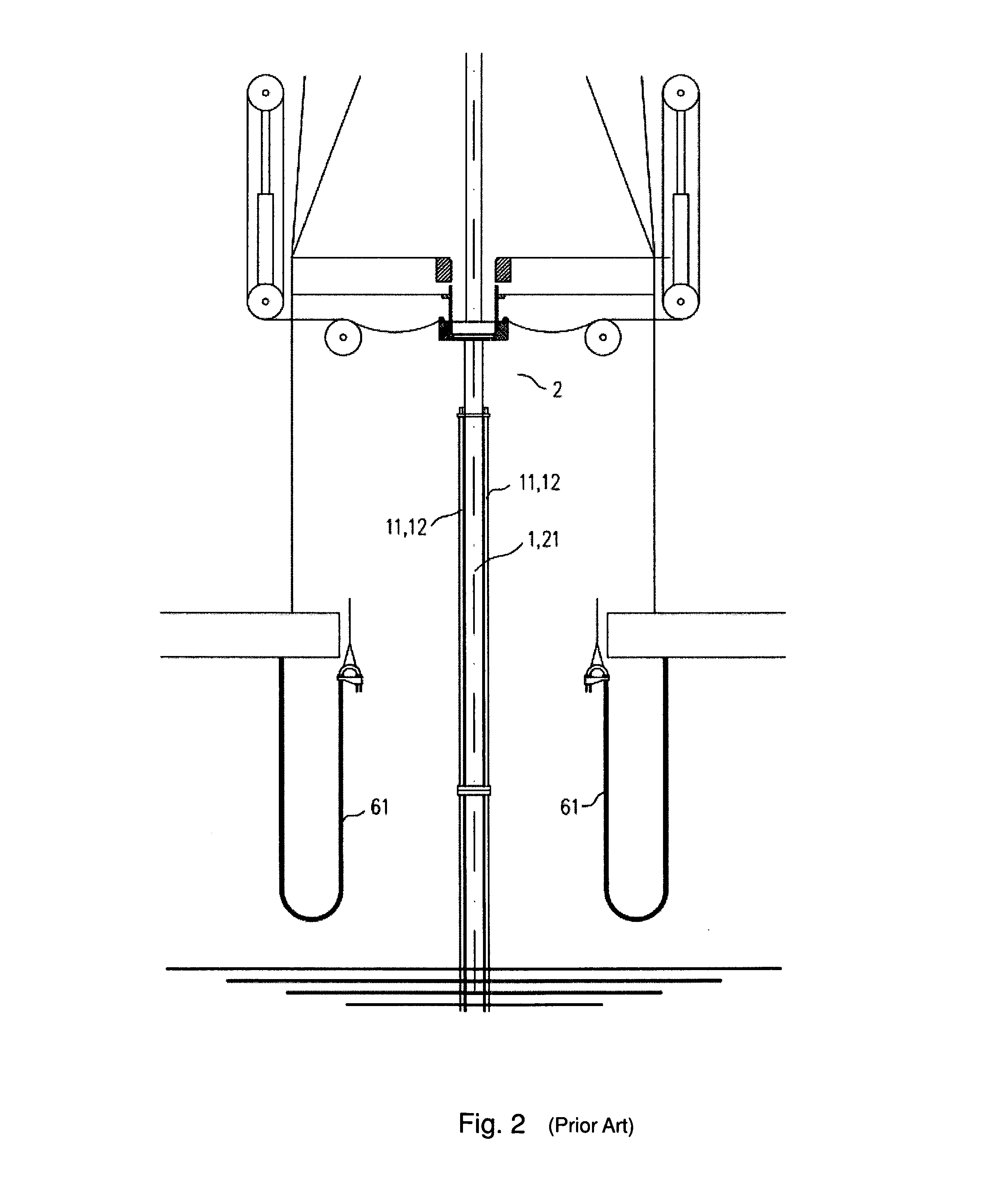
Slip joint (2) comprises a so-called outer barrel (21) which is the lower, static part which follows all the underlying riser sections vertical movements and which in its operative condition is in a locked position relative to the seabed and the well. The slip joint outer barrel (21) envelopes a vertical plain sliding inner barrel (22) which in its operative position should be hung up fixed in the vessel and follow the vertical movements of the vessel, as distinct from the riser (1) and the slip joint outer barrel (21) which thus may be heave compensated.
[0006]The role of the riser (1) is twofold. The riser shall guide the next drill string with a 18⅜″ bit from the rig floor down through the complete riser length, further down through the BOP and the existing 30″ and 20″ casing pipes and drill further down under the 20″ casing pipes' lower end. During this operation it is used a heavier drill mud which is pumped from a drill mud pump system at the rig floor, down through the drill string and out through the bit. The drilling mud washes the bit and the bottom of the hole clean from rock type fragments, and due to the density and the viscous properties of the drill mud, the drill mud brings the rock type fragments back up through the annular space both in the naked bore hole, the cased part with the 20″ casing and out through the well head, BOP and up through the riser, along the outside of the drillstring.

Problems solved by technology

A problem by the prior art is that the vertical connecting manifold usually has to be connected manually together by two ring halves for being arranged around the slip joint, by manual assistance from an operator who hangs in ride belts, before the coupled connecting manifold are lowered down and coupled to the vertical slip joint kill / choke manifold.
The problem related to such vertical connecting comprises several issues: partly to find a quiet moment where the horizontal relative movements are sufficiently quiet to actually conduct the connecting operation, partly that the vertical relative movements may not be fully compensated, partly that the operator must find him / herself in a position where he or she can aim in and steer the movements that are required for the coupling, and partly that the operator needs to hang in ride belts as well both to aim in and to perform the manual operations for coupling the mechanical components or for pulling wires.
However, problems related to a riser and its inherent differential motions relative to a rig are not a problem of that GB publication.

Method used


Image

  • Connecting device for kill/choke lines between a riser and a floating drilling vessel
  • Connecting device for kill/choke lines between a riser and a floating drilling vessel
  • Connecting device for kill/choke lines between a riser and a floating drilling vessel

Examples


Embodiment Construction

[0059]FIG. 9 illustrates an embodiment of the invention. The drawing is a cross-section through a drilling platform through a central portion of the drilling deck and auxiliary platforms below the drilling deck, and through the cellar deck. The drawing is also a cross-section through a moonpool which extends athwart of the vessel and wherein is arranged a skid for a BOP which may be run in from the side and in under the opening in the drilling deck. The riser here hangs from the top drive (not shown) and down through the opening in the drilling deck and the diverter housing and extends further down to the BOP which hangs in a desired elevation above the wellhead. According to this embodiment of the invention, horizontally directed kill- and choke connector manifolds, with kill- and choke hoses from the platform's side, are arranged on the skid and arranged for being guided in into two corresponding and oppositely directed horizontally directed kill- and choke manifolds on the riser'...


PUM


Abstract

A connector device for kill- and choke lines between a riser and a floating drilling platform includes a slip joint on top of the riser including an outer barrel, a kill- and choke manifold arranged on the platform and provided with flexible kill- and choke hoses to the slip joint's outer barrel, and wherein the slip joint's outer barrel is provided with a horizontally directed kill- and choke-manifold.

Description

[0001]This invention relates to a connecting device for kill- and choke hoses at a riser. More specifically it relates to a remote controlled automatic connecting device for kill- and choke hoses between a riser and their adjacent kill- and choke flexible housings from a kill / choke manifold at a rig. A first advantage of the invention is that it facilitates the connecting process due to the horizontal operation instead of the vertical operation wherein the risers pendulum movement otherwise makes the connecting less secure. A second advantage of the invention is that the operator may stand on a place at a distance from the riser and target in and remote-control the connection in a way that one may avoid any operator to hang in riding belts. The operation becomes more secure to the operator and safer due to the easier targeting of the connecting manifold to the riser's kill / choke manifold, in addition the connection may be conducted faster.[0002]Some Background Information: a Short O...

Claims


Application Information

Patent Timeline
Patent Type & Authority Applications(United States)
IPC IPC(8): E21B43/01
CPCE21B17/07E21B19/006E21B19/004
Inventor CHRISTENSEN, OYSTEINKORSMO, ATLE
Owner FUTURE PROD
Why Eureka
Try Eureka