

Portable hydrogen source
a hydrogen source and portable technology, applied in the field of portable hydrogen sources, can solve the problems of increasing the use of hydrogen powered fuel cell systems, increasing bulk and weight, and reformation systems that are not suitable for man-portable applications, so as to prevent the effect of preventing the activation of igniters
- Summary
- Abstract
- Description
- Claims
- Application Information
AI Technical Summary
Benefits of technology
Problems solved by technology
Method used
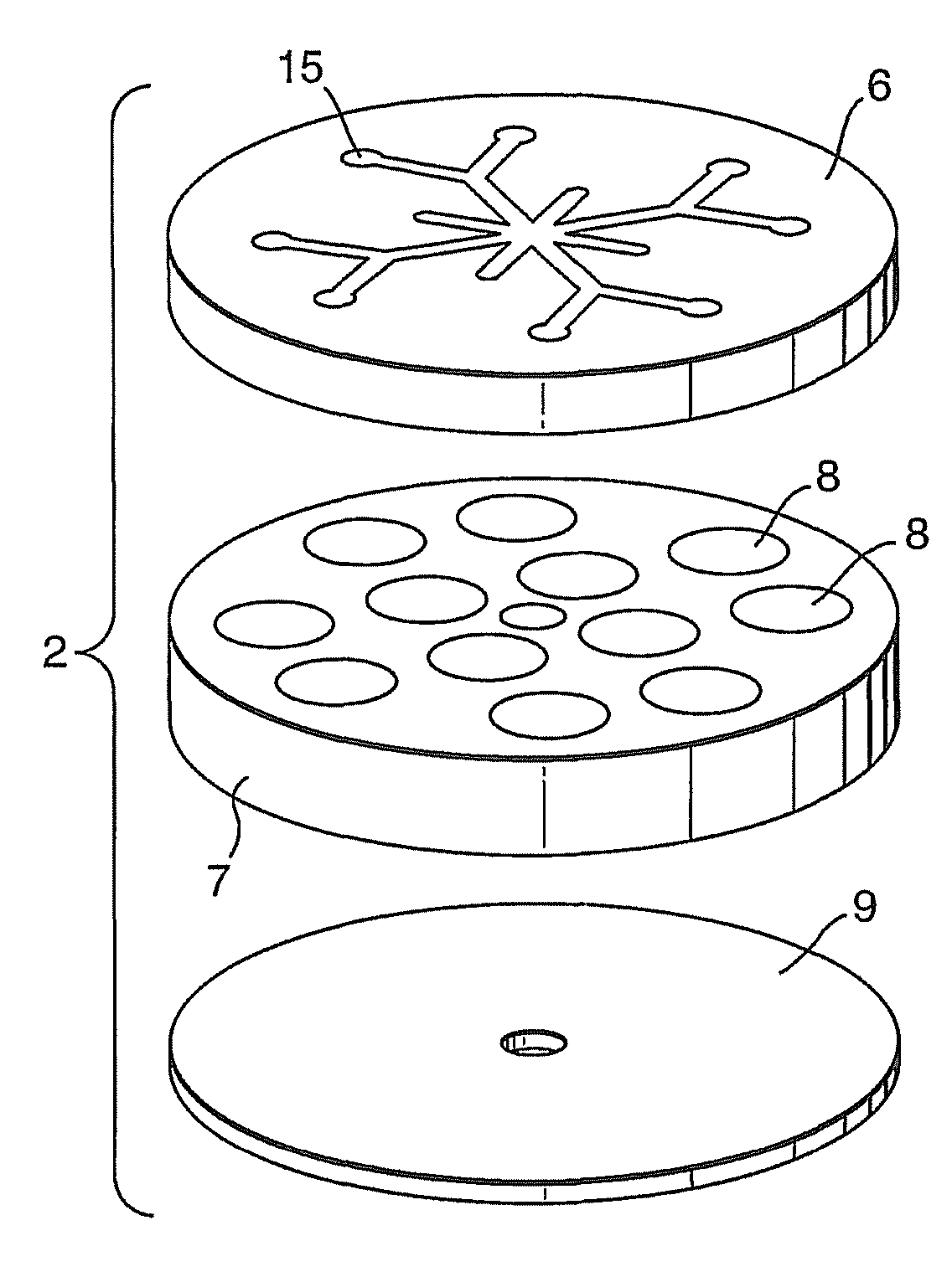
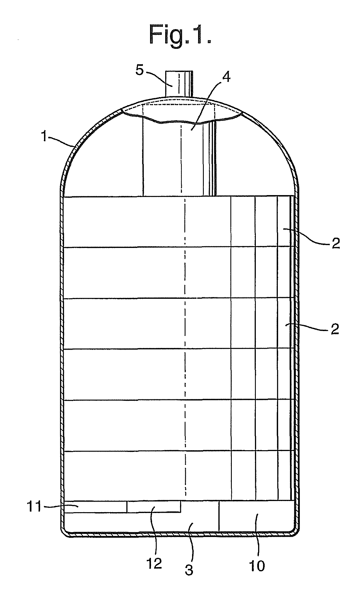
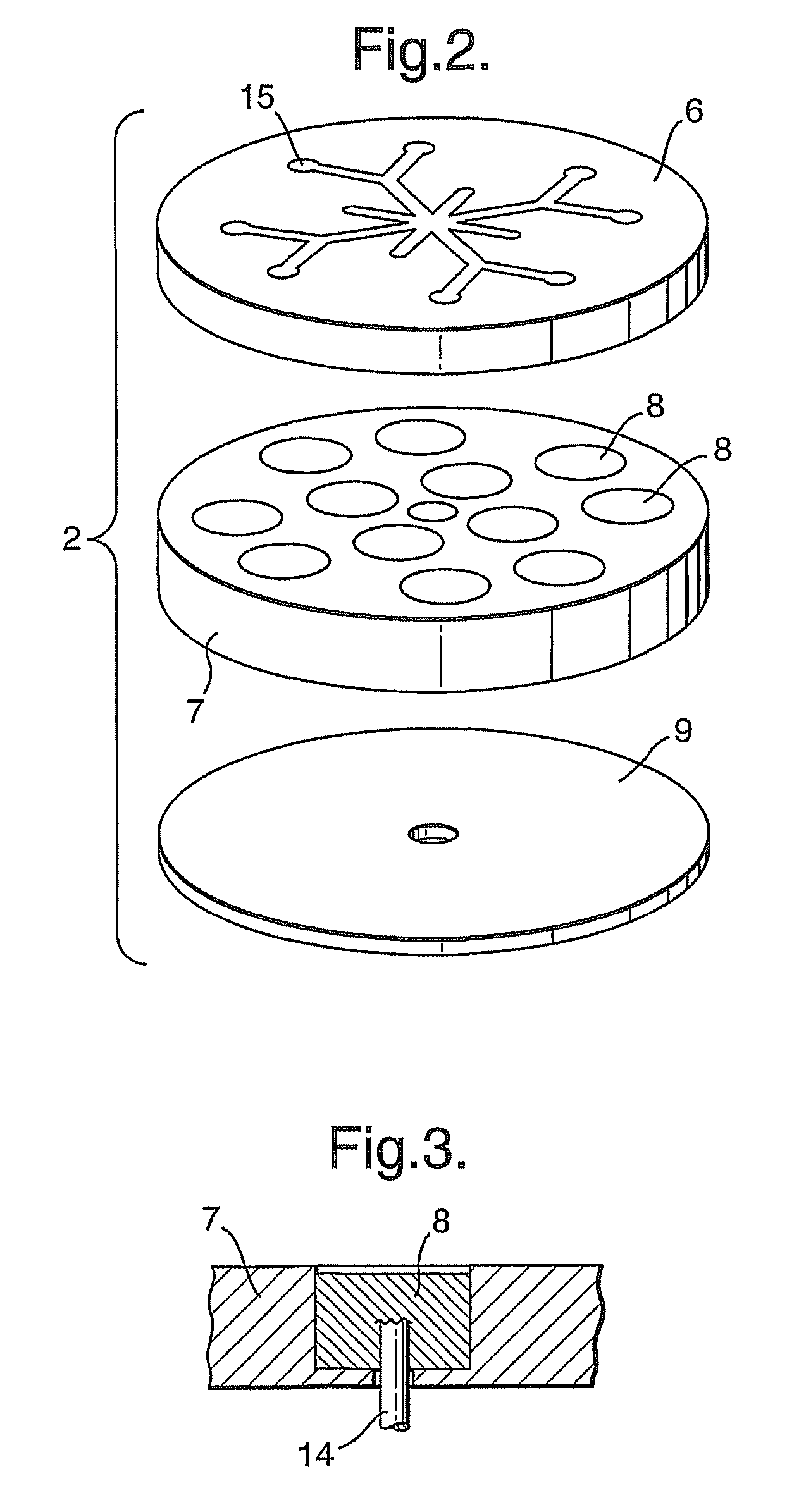
Image

Examples
example 1
[0058]Single cell tests were performed to assess the yields which could be obtained from the thermal decomposition of ammonia borane, in order to determine the optimum ratio of heat mixture to ammonia borane for a given pellet size and configuration. FIG. 9 is a schematic representation of the experimental circuit used for testing pellet decomposition.
[0059]Each cell contains an ammonia borane (90% Aldrich) pellet 36 and one or two heat pellets 37 depending on the type of arrangement. The heat pellet consisting of 86% iron & 14% potassium perchlorate is ignited by a resistive heating wire 38 that is placed at either one end or at each end of the cell, sandwiched between the pellets. The spiral shaped wires used in this example (which could be of any shape or configuration) are manufactured from stainless steel or any suitable high resistive material.
[0060]Experimentally, to decompose a quantity of ammonia borane in a prototype single cell reactor a 5V, 50 ms square pulse is delivere...
example 2
[0064]A bilayer pellet of a different composition was tested. The heat powder used in this experiment was a 1:1 molar mix of lithium aluminium hydride and ammonium chloride. In addition to generating heat this mix also liberates hydrogen and it was hoped that this would increase the hydrogen yield of the total system further. The first and lowermost layer of the pellet contained 0.5 g of the heat mix (LiAlH4+NH4Cl) and the second upper layer 0.5 g of ammonia borane. This pellet was decomposed using a heat resistance wire through which was passed a current pulse of 10 V, 3 A for 50 ms. The hydrogen yield was 1.05 L, 0.086 g H2. This equates to a 8.6% hydrogen by weight based on the weight of the total pellet.
example 3
[0065]In this example bilayer pellets containing the same components as Example 2, but formulated in differing proportions, were formulated and tested. The results of tests where the amount of ammonia borane were varied are summarized in Table 2 below and graphically in FIG. 11.
[0066]In one pellet the first layer contained 0.125 g of the heat mix (LiAlH4+NH4Cl) and the second upper layer 0.6 g of ammonia borane. This pellet was decomposed using a heat resistance wire through which was passed a current pulse of 10 V, 3 A for 3s. The hydrogen yield was 1.0 L, 0.082 g H2. This equates to a yield of 11.4% hydrogen by weight based on the weight of the total pellet.
[0067]
TABLE 2% of wholepellet, whichWt. ofWt. ofis heat% H2 based on% overall H2 yieldVolLiAlH4 / NH4Cl / gNH3BH3 / gpowder:NH3BH3 only(whole pellet)H2 / L0.125111.11%11.48%10.21%1.390.1250.715.15%13.22%11.22%1.120.1250.617.24%13.77%11.40%10.1250.520.00%13.05%10.44%0.790.1250.423.81%13.42%10.23%0.65
PUM
| Property | Measurement | Unit |
|---|---|---|
| diameter | aaaaa | aaaaa |
| diameter | aaaaa | aaaaa |
| weight | aaaaa | aaaaa |
Abstract
Description
Claims
Application Information