
Energy-saving gas burner

A technology for gas stoves and burners, applied in the direction of burners, combustion methods, combustion types, etc., can solve problems affecting safety, waste, insufficient combustion, etc., to solve the burner backfire, improve stability, and improve safety Effect

Inactive Publication Date: 2013-10-23
上海氢城新能源科技有限公司
View PDF7 Cites 0 Cited by
  • Summary
  • Abstract
  • Description
  • Claims
  • Application Information

AI Technical Summary

Problems solved by technology

However, due to the uneven mixing of air and gas in the traditional burner, and the inability to accurately control its ratio, insufficient combustion will result in waste, and the burner is honeycomb-shaped, and insufficient combustion will easily cause tempering and affect safety.

Method used


Image

  • Energy-saving gas burner
  • Energy-saving gas burner
  • Energy-saving gas burner

Examples


Embodiment Construction

[0017] The present invention is further described below in conjunction with specific embodiments.

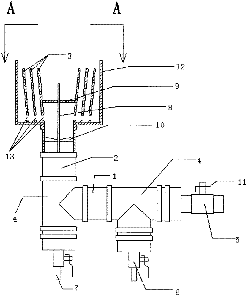
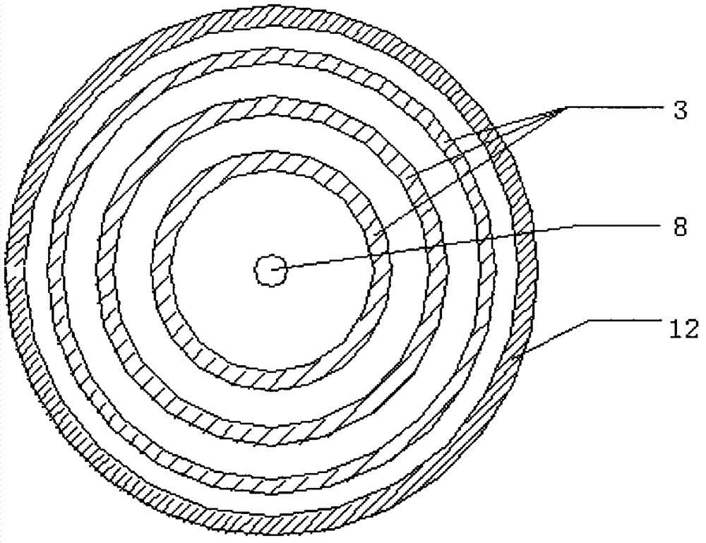
[0018] Such as Figure 1-3 Shown, 1. a kind of energy-saving gas burner head, comprises front road mixing chamber (1), back road mixing chamber (2) and burner head part, and described front road mixing chamber (1) is passed through tee joint (4) respectively It is connected with the air inlet control valve (5) and the gas inlet valve (6); one end of the rear mixing chamber (2) is respectively connected with the front mixing chamber (1) and the water discharge valve (7) through a three-way joint (4) , the other end of the rear mixing chamber (2) is connected to the burner part, and the burner part includes a burner shell (12), a gas distributor (10), a flame tube (8), and a burner sealing plate (9) And the gas guide sleeve (3), the flame tube (8) is located in the center of the furnace head part, and the lower part is connected to the subsequent mixing chamber (2) through the ga...


PUM


Abstract

The invention relates to an energy-saving gas burner which comprises a front mixing chamber, a rear mixing chamber and a burner body. The front mixing chamber is connected with an air intake control valve and a gas intake valve respectively through a three-way joint. One end of the rear mixing chamber is respectively connected with the front mixing chamber and a drain valve through a three-way joint, and the other end of the rear mixing chamber is connected with the burner body. The burner body comprises a burner shell, a gas distribution piece, a flame tube, a burner seal plate and at least two gas guide sleeves; the flame tube is disposed at the center of the burner body, the lower portion of the flame tube penetrates the gas distribution piece to be connected with the rear mixing chamber, the gas guide sleeves inside the burner body are distributed circular around the flame tube, the burner seal plate is arranged inside the circle formed by the gas guide sleeves, and the gas guide sleeves and the burner shell form the angle of 0.5-10 degrees. In addition, guide holes in volute arrangement are formed in the bottoms of the gas guide sleeves.

Description

technical field [0001] The invention relates to an energy-saving gas stove head. Background technique [0002] Energy-saving gas stoves refer to kitchen utensils that use gaseous fuels such as liquefied petroleum gas, artificial gas, and natural gas for direct fire heating. In history, the Frenchman Philip Ruben was the first to develop energy-saving gas stoves. On September 21, 1799, he obtained the patent right for a dual-purpose device for lighting and heating with gas. With the implementation of the new national standard in 2008, enterprises pay more attention to product safety, energy conservation and environmental protection. For gas stoves, the structure of the burner plays a key role in the energy saving of the stove. However, due to the uneven mixing of air and gas in the traditional burner, and the inability to accurately control its ratio, insufficient combustion will result in waste, and the burner is honeycomb-shaped, and insufficient combustion will easily ca...

Claims


Application Information

Patent Timeline
IPC IPC(8): F23D14/02F23D14/46
Inventor 魏银峰
Owner 上海氢城新能源科技有限公司
Learn More