Heat pipe

A heat pipe and pipe body technology is applied in the field of heat pipes with a braided capillary structure, which can solve problems such as general working fluid efficiency, and achieve the effects of improving heat conduction efficiency, reducing backflow resistance, and improving heat pipe performance.

Inactive Publication Date: 2013-10-23
FURUI PRECISE COMPONENT (KUNSHAN) CO LTD +1
View PDF5 Cites 4 Cited by
  • Summary
  • Abstract
  • Description
  • Claims
  • Application Information

AI Technical Summary

Problems solved by technology

[0003] For heat pipes with a braided capillary structure, the traditional method in the industry designs the capillary structure to be woven vertically, horizontally and vertically. This kind of capillary structure has a general efficiency in conducting the working fluid in the longitudinal direction and can only meet the needs of low-power heat pipes.

Method used


Image

  • Heat pipe
  • Heat pipe
  • Heat pipe

Examples


Embodiment Construction

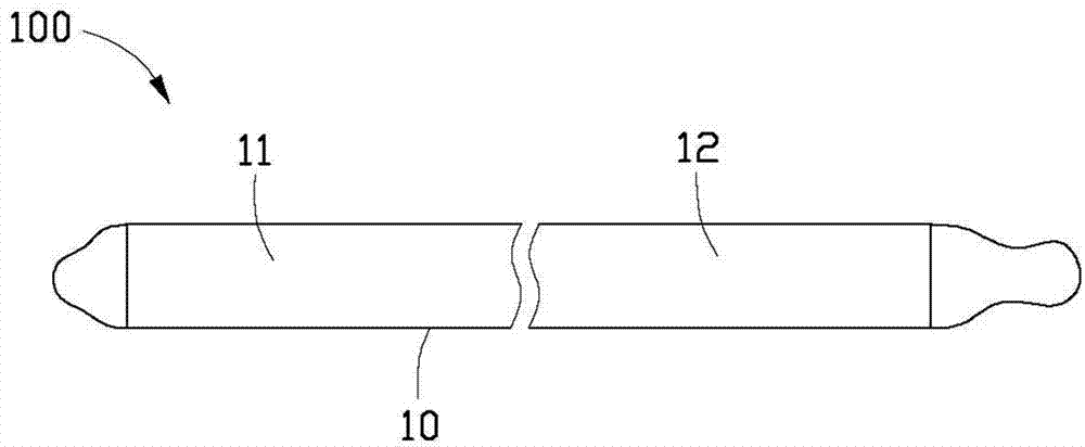
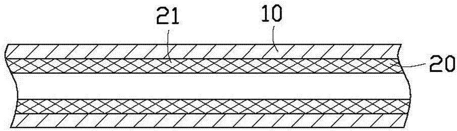
[0019] see Figure 1 to Figure 3 , the heat pipe 100 includes a flat tube body 10, a capillary structure 20 disposed in the tube body 10 and an appropriate amount of working fluid 30 injected into the tube body 10 (see Figure 7 ). The heat pipe 100 includes an evaporation section 11 and a condensation section 12 along the axial direction. In this embodiment, the heat pipe 100 is a thin heat pipe.

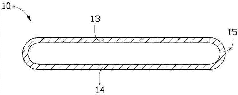
[0020] The pipe body 10 is made of copper and other materials with good thermal conductivity. The tube body 10 is hollow, elongated and flat, and is formed by flattening a circular tube. The thickness of the pipe wall of the pipe body 10 is less than 1.5mm. The tube body 10 includes a top plate 13 , a bottom plate 14 and two side plates 15 . The top plate 13 and the bottom plate 14 are parallel to each other and symmetrical up and down. The two side plates 15 are arc-shaped, respectively located on two sides of the pipe body 10 and connect the top plate 13 and the bottom plate...


PUM


Abstract

An exemplary heat pipe includes a tube, an evaporation section and a condenser section located at two opposite ends of the tube, a grid wick structure received in the tube and abutting an inner wall of the tube, and a working fluid sealed in the tube. The grid wick structure includes a plurality of rhombuses. Each rhombus includes two opposite first included angles, one of the first included angles is at a point of the rhombus nearest one of the ends of the tube, the other first included angle is at a point of the rhombus nearest the other end of the tube. Each first included angle is smaller than 90 degrees.

Description

technical field [0001] The invention relates to a heat pipe, in particular to a heat pipe with a braided capillary structure. Background technique [0002] A heat pipe is a heat transfer component with high heat transfer capacity, fast heat transfer and high thermal conductivity. It can not only transfer a large amount of heat, but also consumes no power, so it is widely demanded by the heat dissipation market. At present, the inner wall of the heat pipe is provided with a wick structure. The wick structure may be a braided mesh with capillary action, which facilitates the transmission of the working fluid in the heat pipe. With the thinning and thinning of electronic products, their heat dissipation requirements continue to increase, making the design of the capillary structure of ultra-thin heat pipes the key to evaluating the heat dissipation performance of electronic products. [0003] For heat pipes with a braided capillary structure, the traditional method in the indu...

Claims


Application Information

Patent Timeline
Patent Type & Authority Applications(China)
IPC IPC(8): F28D15/04
CPCF28D15/04F28D15/0233F28D15/046
Inventor 代升亮罗友梁吴佳鸿
Owner FURUI PRECISE COMPONENT (KUNSHAN) CO LTD
Why Eureka
Try Eureka