Synchronous detector

A technology of synchronous detection and power supply, applied in phase sequence/synchronous indication, circuit breaker testing, etc., can solve problems such as inaccurate results, inaccurate judgment of fault points, prolonging the time for accident handling, etc., and achieve the effect of convenient inspection work

Inactive Publication Date: 2013-10-23
招远市东晟橡胶制品有限公司
View PDF0 Cites 3 Cited by
  • Summary
  • Abstract
  • Description
  • Claims
  • Application Information

AI Technical Summary

Problems solved by technology

[0002] The vacuum circuit breaker of the high-voltage switchgear of the ground substation and the vacuum tube of the underground vacuum switch will have deviations that cannot be detected by the naked eye due to long-term use of the three-phase contacts. It has brought great hidden dangers to the safe power supply work of the mine. Without special instrument detection, it is often difficult to judge the accident point
The traditional monitoring method is to use a multimeter to measure each phase one by one, but cannot simultaneously measure whether the three-phase contacts of the vacuum switch vacuum tube are synchronized. The measurement is very inconvenient and the result is inaccurate. Restricting mine safety production

Method used


Image

  • Synchronous detector

Examples


Embodiment Construction

[0011] The principles and features of the present invention are described below in conjunction with the accompanying drawings, and the examples given are only used to explain the present invention, and are not intended to limit the scope of the present invention.

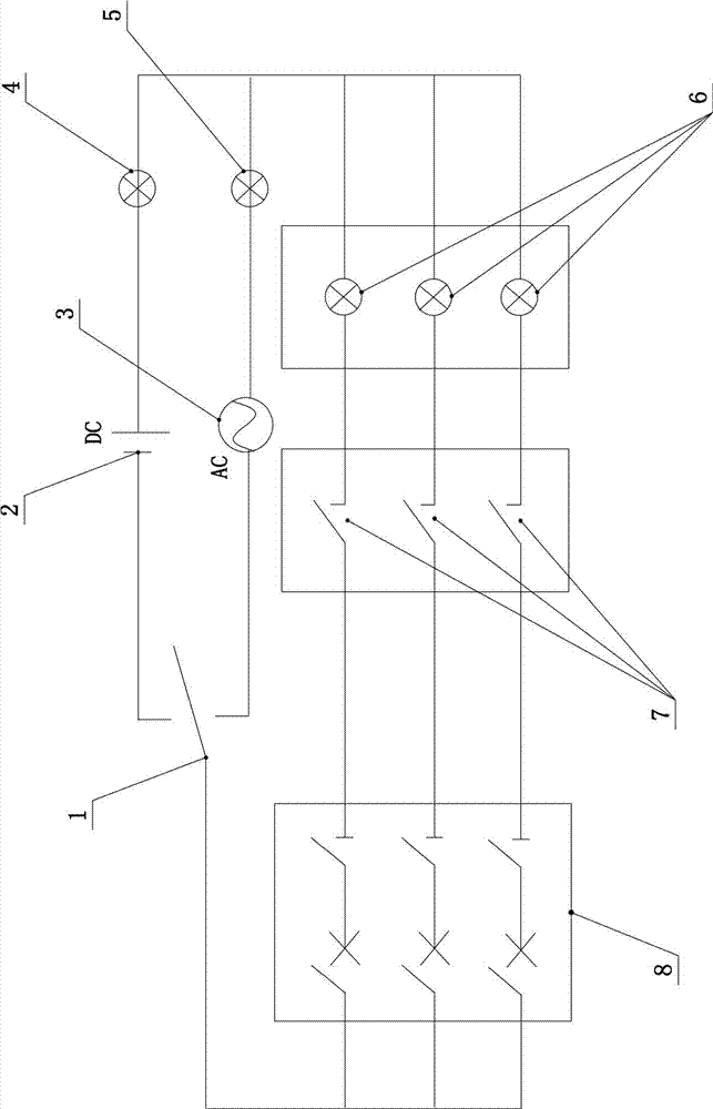
[0012] A synchronous detector, as shown in Figure 1, includes a power supply, the power supply includes a DC power supply 2 and an AC power supply 3 connected in parallel, a DC indicator light 4 is connected in series in the circuit where the DC power supply 2 is located, and a DC indicator light 4 is connected in series in the circuit where the AC power supply 3 is located. There is an AC indicator light 5 in series, one end of the power supply is electrically connected to an AC / DC converter 1, and the AC / DC converter 1 is connected in series with a three-phase circuit breaker 8 through a circuit, and each phase of the three-phase circuit breaker 8 is connected to the other end of the power supply respectively. A co...


PUM


Abstract

Disclosed is a synchronous detector which is convenient to operate and use. The synchronous detector includes a power supply. The power supply includes a direct-current (DC) power supply and an alternating-current (AC) power supply which are mutually connected in a parallel way. A DC indication light is serially connected with a circuit which the DC power supply is in and an AC indication light is serially connected with a circuit which the AC power supply is in. One end of the power supply is electrically connected with an AC-DC converter which is serially connected with a three-phase circuit breaker through a circuit. And a contact point and a signal indication light are serially connected between each phase of the three-phase circuit breaker and the other end of the power supply respectively. Three 1.5V batteries or a 220V AC power supply is selected in the synchronous detector as needed. In use, corresponding yellow, green and red wires are connected at two sides of the circuit breaker or a vacuum tube and the vacuum breaker is switched on step by step so that asynchronous phases can be detected visually through twinkling of bulbs and then adjustment is made until three-phase contacts of the vacuum tube are synchronous. Detection work of maintenance personnel is greatly facilitated.

Description

technical field [0001] The invention relates to a detection instrument, in particular to a vacuum circuit breaker synchronous detection instrument. Background technique [0002] The vacuum circuit breaker of the high-voltage switchgear of the ground substation and the vacuum tube of the underground vacuum switch will have deviations that cannot be detected by the naked eye due to long-term use of the three-phase contacts. It has brought great hidden dangers to the safe power supply work of the mine. Without special instrument detection, it is often difficult to judge the accident point. The traditional monitoring method is to use a multimeter to measure each phase one by one, but cannot simultaneously measure whether the three-phase contacts of the vacuum switch vacuum tube are synchronized. The measurement is very inconvenient and the result is inaccurate. It restricts mine safety production. Contents of the invention [0003] The invention aims at the disadvantages and...

Claims


Application Information

Patent Timeline
Patent Type & Authority Applications(China)
IPC IPC(8): G01R31/327G01R29/18
Inventor 石德龙
Owner 招远市东晟橡胶制品有限公司
Why Eureka
Try Eureka