Tandem type hydrodynamic force sound wave generation device

A hydrodynamic and sound wave generation technology, which is applied in the directions of sound-generating equipment, shaking/oscillating/vibrating mixers, and dissolving, etc., to achieve the effects of stable operation, easy growth and collapse, and simple structure

Inactive Publication Date: 2014-09-03
SHAANXI NORMAL UNIV
View PDF4 Cites 0 Cited by
  • Summary
  • Abstract
  • Description
  • Claims
  • Application Information

AI Technical Summary

Problems solved by technology

[0004] In order to overcome the shortcomings of the single reed whistle ultrasonic generating device in the prior art, the present invention provides a series hydrodynamic sound wave generating device with simple structure, strong cavitation effect, and high fluid mixing and emulsifying efficiency

Method used


Image

  • Tandem type hydrodynamic force sound wave generation device
  • Tandem type hydrodynamic force sound wave generation device
  • Tandem type hydrodynamic force sound wave generation device

Examples


Embodiment 1

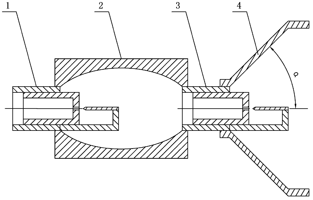
[0023] Depend on figure 1 It can be seen that the serial hydrodynamic sound wave generating device of this embodiment is composed of the first nozzle 1 , the cavity 2 , the second nozzle 3 and the reflector 4 .

[0024] The cavity 2 of this embodiment is a hollow cylinder with an elliptical inner cavity axial section, a first nozzle 1 is installed on the front port of the cavity 2, a second nozzle 3 is installed on the rear port of the cavity 2, and the second nozzle 3 is installed on the rear port of the cavity 2. The centerlines of one nozzle 1 and the second nozzle 3 are on the same straight line.

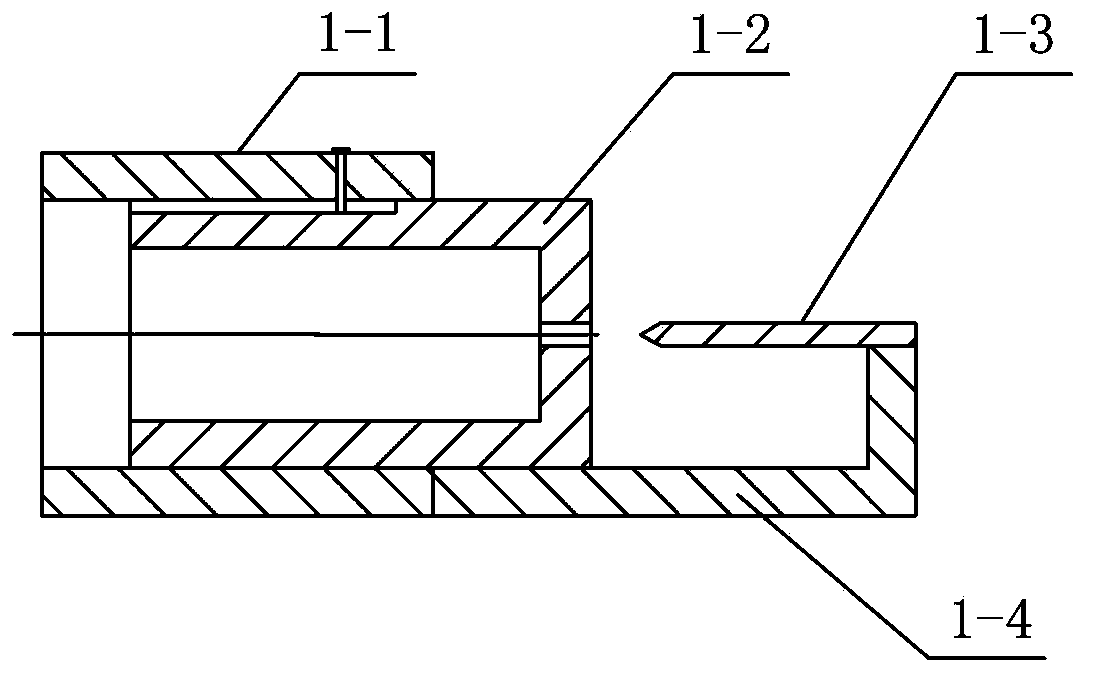
[0025] see figure 2 , the first nozzle 1 of this embodiment is composed of a first outer cylinder 1-1, a first inner cylinder 1-2, a first reed 1-3 and a first connecting rod 1-4. The first outer cylinder 1 -1 is fixedly connected with the front side wall of the cavity 2 by threads, the first inner cylinder 1-2 is sleeved on the inner wall of the first outer cylinder 1-1, and...

Embodiment 2

[0030] The bottom of the first inner cylinder 1-2 of this embodiment is processed with a first rectangular nozzle hole, which is located at the focal point of the long axis of the cavity 2, and has a length of 15 mm, a width of 1.5 mm, and a depth of 5 mm. A first reed 1-3 is installed at a position of 2 mm outside the first rectangular spray hole, and the end of the first reed 1-3 is connected to the wall of the first outer cylinder 1-1 by the first connecting rod 1-4. Integral structure, the first reed 1-3 is made of ductile stainless steel, its length is 20mm, thickness is 1.2mm, the width is the same as the length of the first rectangular spray hole, the first reed 1-3 is the same as the first rectangular nozzle The top facing the nozzle hole is processed into an isosceles triangle with an apex angle of 25°.

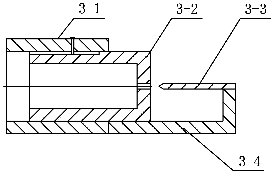
[0031] The bottom of the second inner cylinder 3-2 of the present embodiment is processed with a second rectangular spray hole, the length of the second rectangular ...

Embodiment 3

[0034] The bottom of the first inner cylinder 1-2 of this embodiment is provided with a first rectangular spray hole, the first rectangular spray hole is located at the focal point of the long axis of the cavity 2, and its length is 20mm, width is 2.0mm, and depth is 15mm. A first reed 1-3 is installed at a position 10 mm outside the first rectangular spray hole, and the end of the first reed 1-3 is connected to the wall of the first outer cylinder 1-1 by the first connecting rod 1-4. Integral structure, the first reed 1-3 is made of ductile stainless steel, its length is 40mm, thickness is 2.0mm, the width is the same as the length of the first rectangular spray hole, the first reed 1-3 is the same as the first rectangular nozzle The top facing the spray hole is processed into an isosceles triangle with an apex angle of 35°.

[0035]The bottom of the second inner cylinder 3-2 of the present embodiment is provided with a second rectangular spray hole with a length of 20 mm, a ...


PUM


Abstract

The invention relates to a tandem type hydrodynamic force sound wave generation device. The tandem type hydrodynamic force sound wave generation device is characterized in that the front end of a cavity is provided with a first spray nozzle connected with a fluid pipeline, the back end of the cavity is provided with a second spray nozzle, the center lines of the first nozzle and the second nozzle are on the same straight line, and a divergent reflector is arranged on the outer wall of the second spray nozzle; the first spray nozzle and the second spray nozzle are connected in series through an oval cavity, two spring pieces can be used for generating different sound wave frequencies, and sound waves generated by the second spring piece are reflected by the inner wall of a reflector and then propagate along the divergent reflector, so that the generated sound waves have directivity. In addition, the tandem type hydrodynamic force sound wave generation device has the advantages of strong cavitation effect, high fluid mixing and emulsifying efficiency, simple structure, stable operation and relatively low cost; and as the movable spray nozzles can be changed and adjusted according to practical requirements, the tandem type hydrodynamic force sound wave generation device is suitable for industrialized application.

Description

technical field [0001] The invention belongs to the technical field of ultrasonic mixing or emulsification, and in particular relates to a serial hydrodynamic sound wave generator capable of realizing efficient mixing or emulsification of fluids. Background technique [0002] At present, the reed whistle has been extensively studied and explored as a fluid dynamic sounding device. The jet liquid excites the reed to vibrate to generate ultrasonic waves. Under the action of reed vibration and sound waves, cavitation bubbles grow and collapse to produce cavitation. Oil and water are mixed or emulsified together with high temperature and high pressure generated by cavitation and sonic vibration. [0003] However, most of the sounding devices use a single reed whistle. Usually, the fluid still has a lot of kinetic energy after impacting the reed whistle, and this part of kinetic energy is often not properly utilized, which leads to relatively low efficiency of the sounding device...

Claims


Application Information

Patent Timeline
Patent Type & Authority Patents(China)
IPC IPC(8): G10K11/00B01F11/02B01F3/08
Inventor 吴胜举李凤鸣邸惠芳沈壮志
Owner SHAANXI NORMAL UNIV
Why Eureka
Try Eureka